
Intra-corporeal surgical retractor

a surgical retractor and intracorporeal technology, applied in the field of surgical retractors, can solve the problems of organs or tissues that are difficult to position or mold properly sponges and gauze, sponges and gauze are extremely flexible and pliant, and do not offer much resistance, and achieve the effect of being used readily

Active Publication Date: 2012-10-09
BODENSTEIN LAWRENCE
View PDF11 Cites 19 Cited by
  • Summary
  • Abstract
  • Description
  • Claims
  • Application Information

AI Technical Summary

Benefits of technology

[0011]It is an object of the invention to provide a surgical retractor or tissue displacement device which can be used readily in a variety of surgical applications.
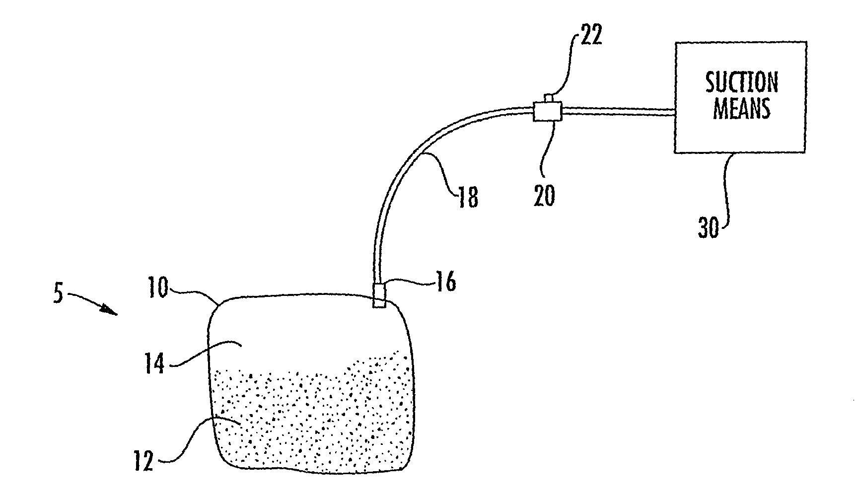
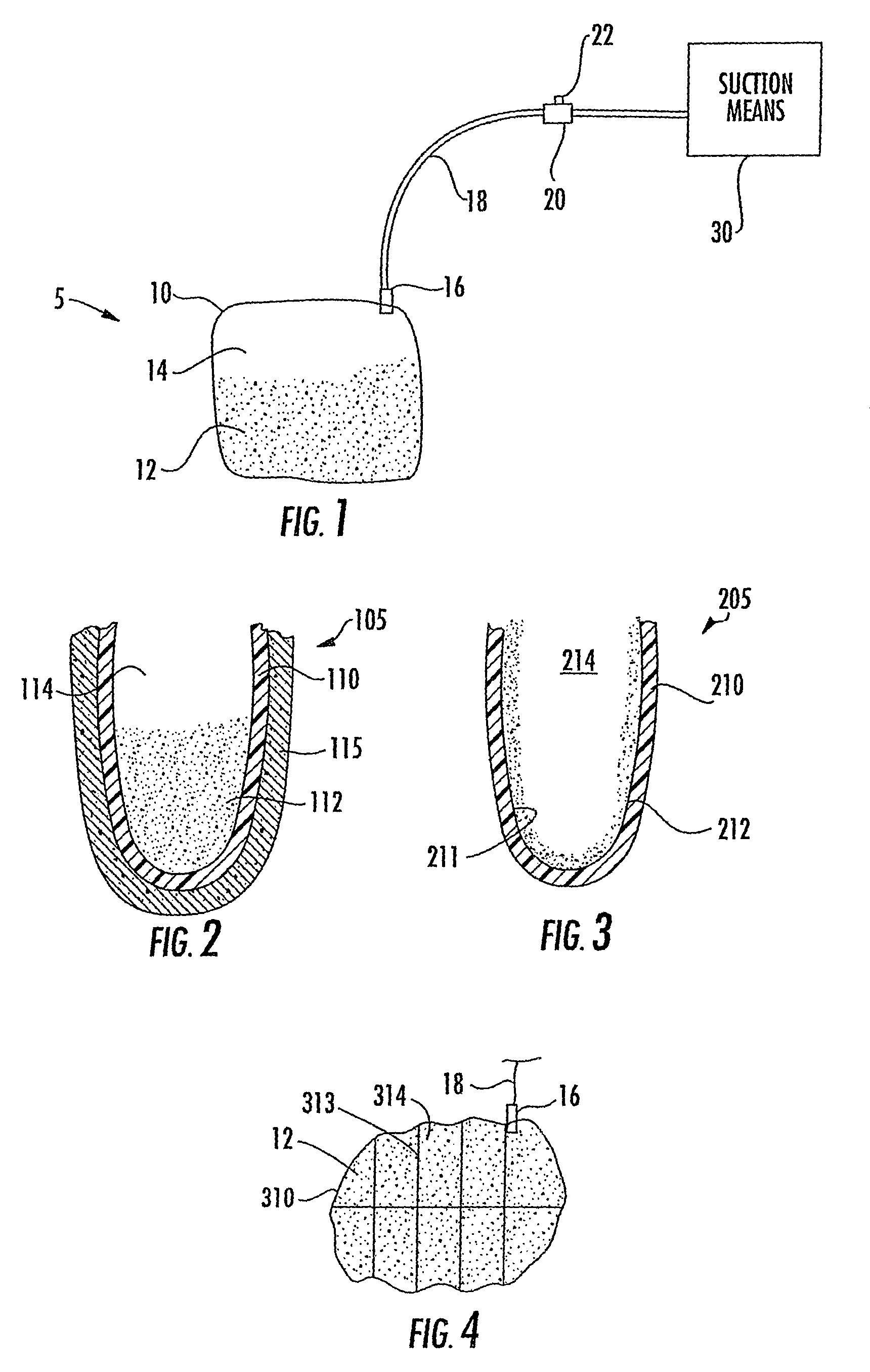
[0015]One embodiment of the invention is a tissue displacement surgical retractor, which includes a sealed container, made from a flexible material, having an interior containing a granular substance and a fluid (e.g., a gas). At least one tube is provided with one end attached to the container in communication with the interior of the container and the other end connected to a suction mechanism. The surgical retractor is placed on a body site. Since the sealed container is a flexible material the retractor can easily conform to the body site and readily form a bottom surface which sits on the body site. When the fluid is evacuated from the container, the container constricts around the granular substance and becomes relatively rigid. The device is first molded around the tissue or organ with the tissue or organ in the desired position. The fluid (e.g., air) is evacuated, and the device retains its shape. The granular substance comprises sufficient ballast or weight so that it remains in place where positioned at the body site to perform the retraction functions. As a result, the organ or tissue is retained in place. An absorbent sleeve or layer may be provided surrounding the container.
[0016]The granular substance is preferably substantially incompressible; it may be provided as loose fill or as a layer over at least a portion of the inner wall. If provided as loose fill, the granular substance is preferably a biologically compatible material safely absorbable by the human body. The first end of the tube preferably includes a filter to prevent the granular substance from being evacuated along with the fluid. If provided in a layer over at least a portion of the inner wall, the granular substance prevents the slippage of one wall of the container against the other, and the device retains its shape.

Problems solved by technology

First, surgical sponges and gauze are extremely flexible and pliant and do not offer much resistance.
As a result, the organ or tissue has a tendency to flop over or push the sponge or gauze out of the way.
Additionally, sponges and gauze are difficult to position or mold properly in the first place.
Since the field is filled with bodily fluids, the sponges are constantly absorbing those fluids, which has a deleterious effect on the sponges' rigidity and ability to keep back the organ or tissue.
A detriment to Clark's device is that the device cannot be molded to fit a specific irregular space or retain a variety of different structures as it is non-malleable.
There is also a potential risk of injuring the tissue by application of the vacuum suction.
This device works suitably as a sponge, however it fails as a retractor that does not react at all with the organs or tissues it retains, because it is constantly absorbing fluid.
All of the above references teach devices which cannot be used with minimally invasive surgical procedures (e.g., laparoscopy, retroperitoneoscopy, thoroscopy) and are limited in their ability to be molded into a specific shape.

Method used


Image

  • Intra-corporeal surgical retractor
  • Intra-corporeal surgical retractor

Examples


first embodiment

[0030]FIG. 2 depicts a partial sectional view of the pouch of the invention. Device 105 includes a plastic or polymer pouch 110 having loose granular fill 112 disposed therein. Space 114 is also provided as explained above. The minimum amount of space required in pouch 110 is only enough to allow the granular material 112 to shift and be malleable. Additional space could be provided.

second embodiment

[0031]FIG. 3 depicts a partial sectional view of the invention. Device 205 includes a plastic or polymer pouch 210 as before. However, instead of containing loose granular fill, pouch 210 is provided with a rough or coarse granular surface inner coating 212. Interior 214 of pouch 210 is substantially empty. When the air is evacuated from the pouch, the interior walls 211 of the pouch come into contact with one another, as indicated by arrows A in FIG. 3. The extremely high coefficient of friction between mating inner coating surfaces prevents the pouch 210 from moving or deforming substantially, and pouch 210 becomes rigid. It is also contemplated to provide simply an extremely rough surface that is not necessarily made from a layer of granular material being applied to the interior walls 211 of the pouch 205.

[0032]FIG. 4 depicts a partial schematic view of a third embodiment of the invention. Like the first embodiment, pouch 310 contains loose granular material 12. However, the int...


PUM


Abstract

An intra-corporeal surgical retractor for holding tissues and organs in place is provided, including a sealed container, made from a flexible material, having an interior containing a granular substance and a fluid. At least one tube may be provided with one end attached to the container in communication with the interior of the container and the other end connected to a suction mechanism. When the fluid is evacuated from the container, the container constricts around the granular substance and becomes relatively rigid. An absorbent sleeve or layer may be provided surrounding the container. The granular substance may be provided as loose fill or as a layer over at least a portion of the inner wall. Alternatively, the inner walls of the container may be provided with a very rough surface. Further, the outer surface of the bottom of the pouch is enhanced frictionally.

Description

RELATED APPLICATIONS[0001]This application claims domestic priority from U.S. Provisional Patent Application No. 60 / 377,682, filed on May 4, 2002 and is a continuation-in-part of U.S. Non-Provisional patent application Ser. No. 10 / 167,350, filed on Jun. 11, 2002 and incorporates all of the teachings therein here by reference.BACKGROUND OF THE INVENTION[0002]1. Field of the Invention[0003]The invention relates to surgical devices, and more specifically to surgical retractors for displacing organs and tissues and maintaining them in a specific position in a surgical environment.[0004]2. Description of the Related Art[0005]During surgery, a physician will typically work on a small area or portion of a patient and will need to push the organs and tissues that are not being treated away from the area in question. Alternatively, a physician may need to treat the underside of an organ (or another inconvenient or difficult to reach surface or section) and will need to prop it up for an exte...

Claims


Application Information

Patent Timeline
IPC IPC(8): A61B1/32
CPCA61B1/313A61B1/32A61B17/02A61B2017/00561A61B2017/0212
Inventor BODENSTEIN, LAWRENCE
Owner BODENSTEIN LAWRENCE
Learn More