Power receiver, and electronic apparatus and non-contact charger using same

a technology of power receiver and charger, which is applied in the direction of electrochemical generator, safety/protection circuit, transportation and packaging, etc., can solve the problems of defective charging, reduced weight of electronic equipment, limited secondary battery capacity, etc., and achieve the effect of reducing charging efficiency and suppressing heat generation

Active Publication Date: 2012-10-09
KK TOSHIBA +1
View PDF18 Cites 31 Cited by
  • Summary
  • Abstract
  • Description
  • Claims
  • Application Information

AI Technical Summary

Benefits of technology

[0007]According to an aspect of the present invention, there are provided a power receiver which can suppress heat generation and a decrease in charging efficiency due to eddy current by suppressing the eddy current generated in the power receiving side by electromagnetic induction, and an electronic apparatus and a non-contact charger using the same.

Problems solved by technology

At present, the capacity of the secondary battery is limited, and it is required to recharge once per several days to several weeks.
But, the weight of the electronic apparatus has been reduced with the downsizing and weight reduction of the electronic apparatus in these years, and the contact pressure between the electrode of the power receiver and the electrode of the power feeder becomes insufficient, causing a problem of defective charging.
But, the ferrite becomes brittle and has poor impact resistance when it is fabricated into a thin form, and the power receiver tends to have a malfunction if equipment is dropped.
But, magnetic flux passing through the planar coil is interlinked with the substrate and the like within the equipment, so that there is a problem that heat is produced within the device because of an eddy current generated by the electromagnetic induction.
Therefore, high electric power cannot be transmitted, and a charging time becomes long as a result.
As described above, the power receiver applying the conventional non-contact charging method fails to take sufficient measures against the eddy current generated by the electromagnetic induction.
Besides, since the power receiver is attached to the electronic apparatus main body, the heat generation has an adverse effect on the circuit parts and the like.
Therefore, high electric power cannot be transmitted when charging, resulting in a problem of having a long charging time.
The generation of the eddy current also induces the generation of noise, becoming a factor for degrading the charging efficiency.

Method used


Image

  • Power receiver, and electronic apparatus and non-contact charger using same
  • Power receiver, and electronic apparatus and non-contact charger using same
  • Power receiver, and electronic apparatus and non-contact charger using same

Examples


example 1

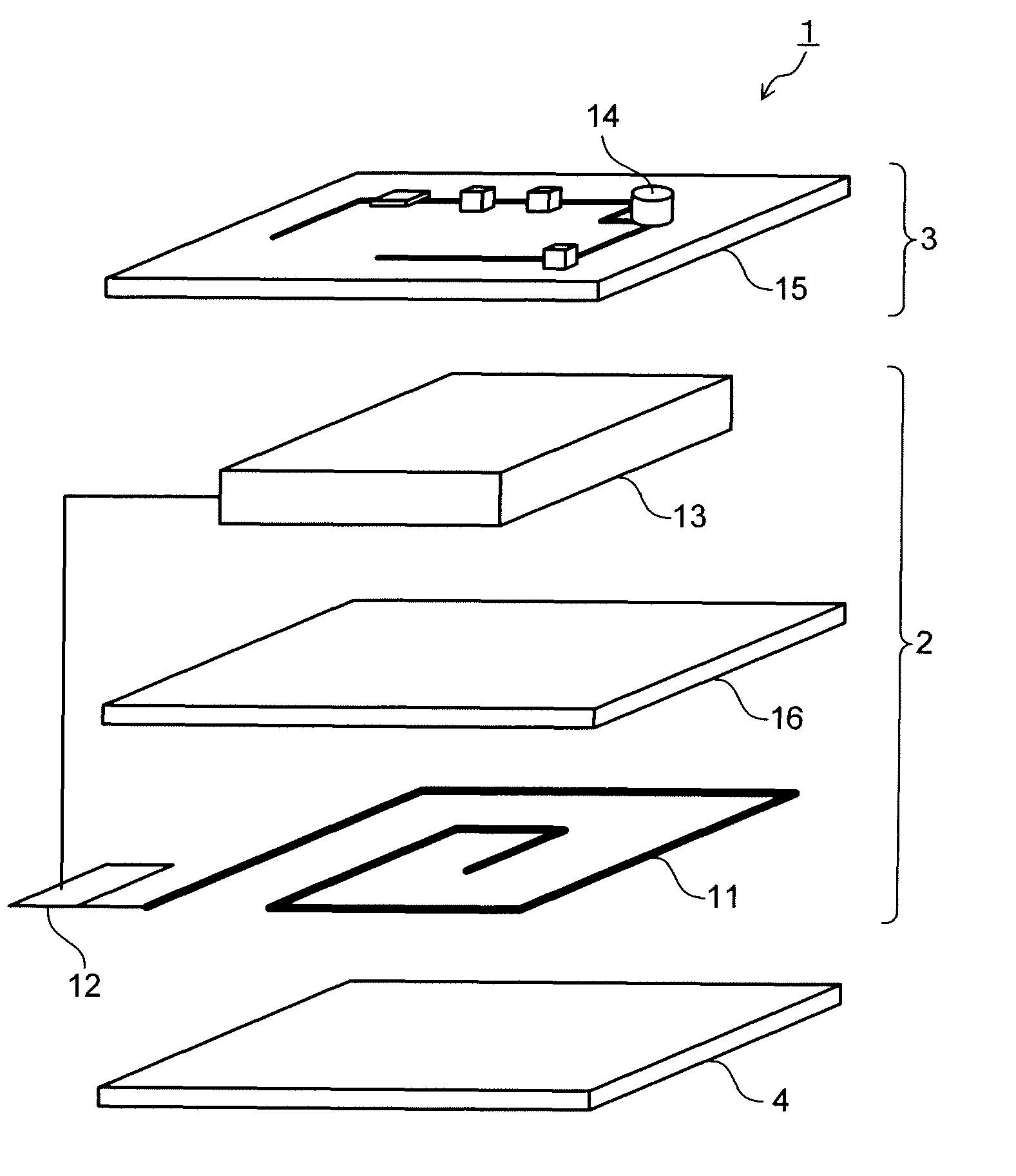
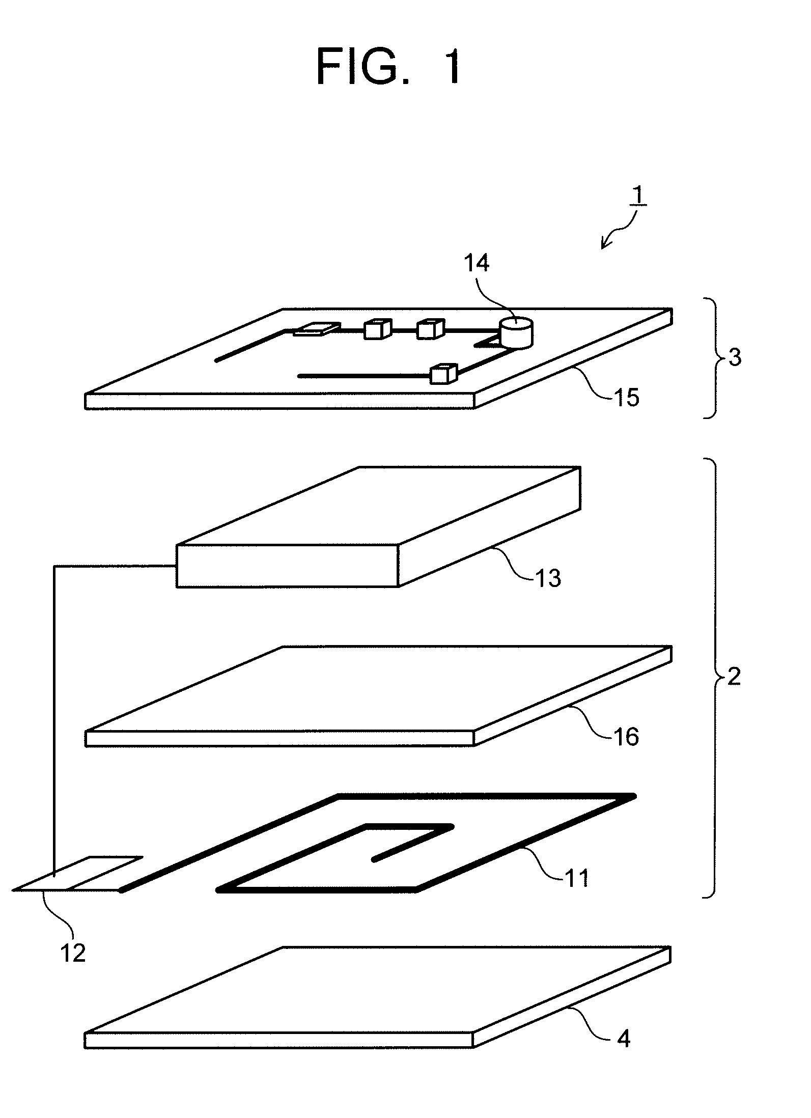
[0072]As a magnetic foil, an amorphous alloy strip having an average thickness of 15 μm and a composition of Co74Fe4Si8B14 (atomic ratio) was prepared. A protruded amount of an outer peripheral portion of the amorphous alloy strip was determined to be do=6 mm, and three of the amorphous alloy strips were stacked. The three amorphous alloy strips were disposed between the second coil (power receiving coil 11) and the secondary battery 13 as shown in FIG. 1. A cellular phone and a non-contact charger using a power receiver having the above magnetic foil were determined as Example 1.

examples 2 to 5

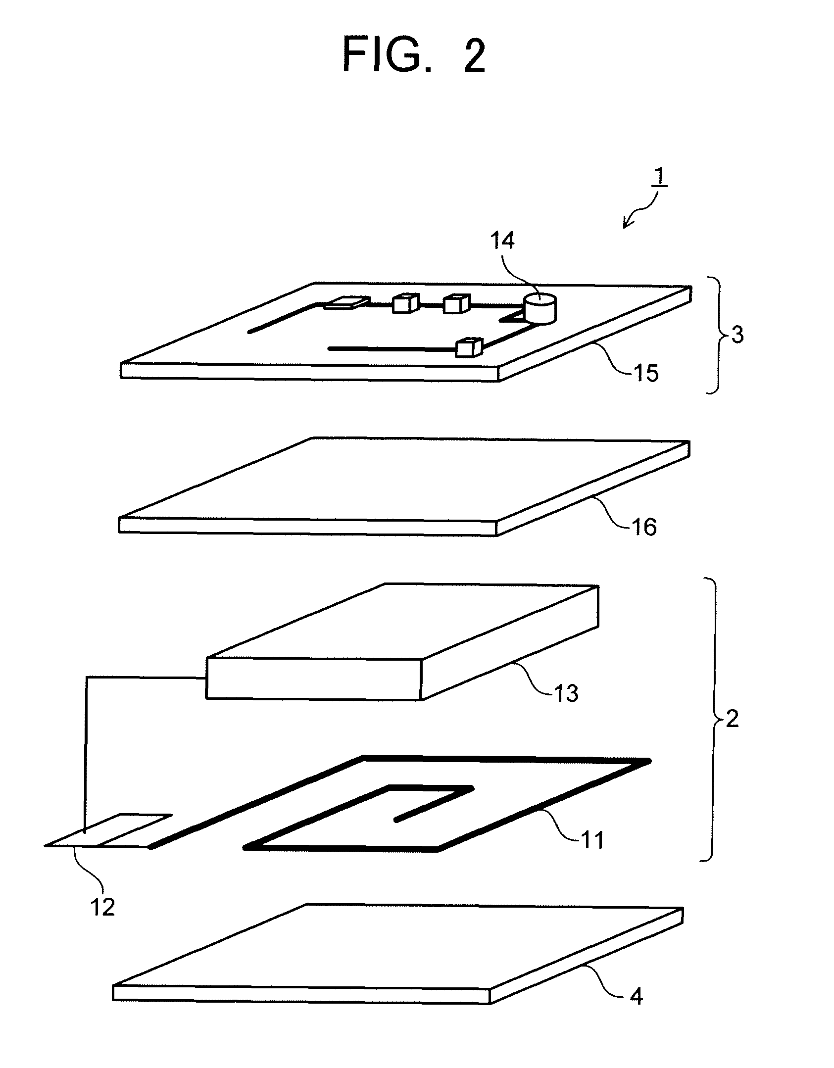
[0073]In Example 2, three amorphous alloy strips having the outer peripheral portion with a protruded amount of do=3 mm were stacked. In Example 3, three amorphous alloy strips having do=0 mm were stacked. In Example 4, three amorphous alloy strips having the outer peripheral portion with a protruded amount of do=−3 mm were stacked. In Example 5, a single amorphous alloy strip having the outer peripheral portion with a protruded amount of do=6 mm was used. Those amorphous alloy strips were disposed between the second coil (power receiving coil 11) and the circuit board 15 in the same manner as in Example 1 to configure the power receivers. Cellular phones and non-contact chargers using the above power receivers were determined as Examples 2 to 5.

example 6

[0074]The protruded portion (do=6 mm) of the same amorphous alloy strip as in Example 1 was bent to form a bent portion as shown in FIG. 5. Three of such amorphous alloy strips were stacked and disposed between the second coil (power receiving coil 11) and the circuit board 15 in the same manner as in Example 1 to configure the power receiver. A cellular phone and a non-contact charger using the above power receiver were determined as Example 6.


PUM

PropertyMeasurementUnit
thicknessaaaaaaaaaa
thicknessaaaaaaaaaa
thicknessaaaaaaaaaa

Abstract

An electronic apparatus (1) includes a power receiver (2) and an electronic apparatus main body (3). The power receiver (2) includes a power receiving coil (11) having a spiral coil, a rectifier (12) and a secondary battery (13). The electronic apparatus main body (3) includes an electronic device (14) and a circuit board (15). A magnetic foil (16) is arranged in at least one position between the spiral coil (11) and one of the secondary battery (13), the rectifier (12), the electronic device (14) and the circuit board (15).

Description

TECHNICAL FIELD[0001]The present invention relates to a power receiver which is applied to non-contact charging, and an electronic apparatus and a non-contact charger using the same.BACKGROUND ART[0002]The development of portable telecommunications equipment is remarkable in these years, and especially cellular phones are being made smaller and lighter quickly. In addition to the cellular phones, electronic apparatuses such as video cameras (handy cameras etc.), cordless telephones, laptop personal computers (notebook personal computers) and the like are also being made smaller and lighter. They have a secondary battery provided within an electronic apparatus main body so as to be usable without connection to a wall outlet. Thus, their portability and usability are enhanced. At present, the capacity of the secondary battery is limited, and it is required to recharge once per several days to several weeks.[0003]Recharging methods include a contact charging method and a non-contact ch...

Claims


Application Information

Patent Timeline
Patent Type & Authority Patents(United States)
IPC IPC(8): H02J7/00H01F27/36H01F38/14
CPCH02J7/025H01M10/46H01F27/365H01F38/14H02J50/10H02J7/00302H02J50/70H01F27/36Y02E60/10H01F27/361H01F27/366H02J50/12H02J5/00
Inventor INOUE, TETSUOKUSAKA, TAKAOSUZUKI, MASAHARU
Owner KK TOSHIBA
Why Eureka
Try Eureka