Long range phasing voltmeter

a phasing voltmeter and long-range technology, applied in the direction of voltage-current phase angle, phase sequence/synchronization indication, instruments, etc., can solve the problems of individual phase identification loss, inability to accurately identify individual conductors, and loss of phase identification, so as to achieve accurate determination of phase difference

Active Publication Date: 2012-10-09
BIERER WALTER S
View PDF9 Cites 24 Cited by
  • Summary
  • Abstract
  • Description
  • Claims
  • Application Information

AI Technical Summary

Benefits of technology

[0011]According to its major aspects and briefly recited, the present invention is a long-range, wireless, phasing voltmeter system that determines the instantaneous phase angle difference between two electrical conductors. To make that determination, a signal containing voltage and phase information is sent, possibly over a distance of many miles, from a reference voltage source proximate to an electrical conductor serving as a reference conductor to a meter probe proximate to an electrical conductor in the field. Between the reference source and the meter probe are a first unit and a second unit. The first unit may be very close to the reference probe; the second unit may be very close to the meter probe. The first unit sends a signal containing the voltage and phase information it has received from the reference probe to the second unit which forwards the voltage and phase information to the meter probe. The signal that is transmitted from the first unit to the second unit is the instantaneous voltage of that reference conductor and the phase difference between the frequency of the voltage that reference conductor carries and a known frequency serving as a standard frequency. This phase difference, when received by the second unit, is used in conjunction with the same known, standard frequency to produce a surrogate for the original instantaneous voltage carried by the reference conductor. It is the surrogate signal that is then sent to the meter probe for comparison to the voltage information on the field conductor. The result of this method is an accurate determination of the phase difference between the two conductors, regardless of the distance separating them.

Problems solved by technology

Unfortunately, individual phase identification may get lost in overhead distribution and transmission systems.
In underground electrical systems, which may extend for many miles, the phase identification ascribed to individual conductors is not always correct.
Unauthorized digging or trenching up of an underground electrical system, which is a common occurrence, may result in loss of phase identification.
Also, natural disasters such as accidents, hurricanes, tornadoes, forest fires, high winds, snow, ice, earthquakes, floods, etc. may result in loss of phase identification in above-ground and even in underground transmission systems.
Determining the time varying voltages of two conductors is part of the measurement but when the conductors are far enough apart, the fact that they are separated introduced errors into the comparison of the two measurements.

Method used


Image

  • Long range phasing voltmeter
  • Long range phasing voltmeter
  • Long range phasing voltmeter

Examples


Embodiment Construction

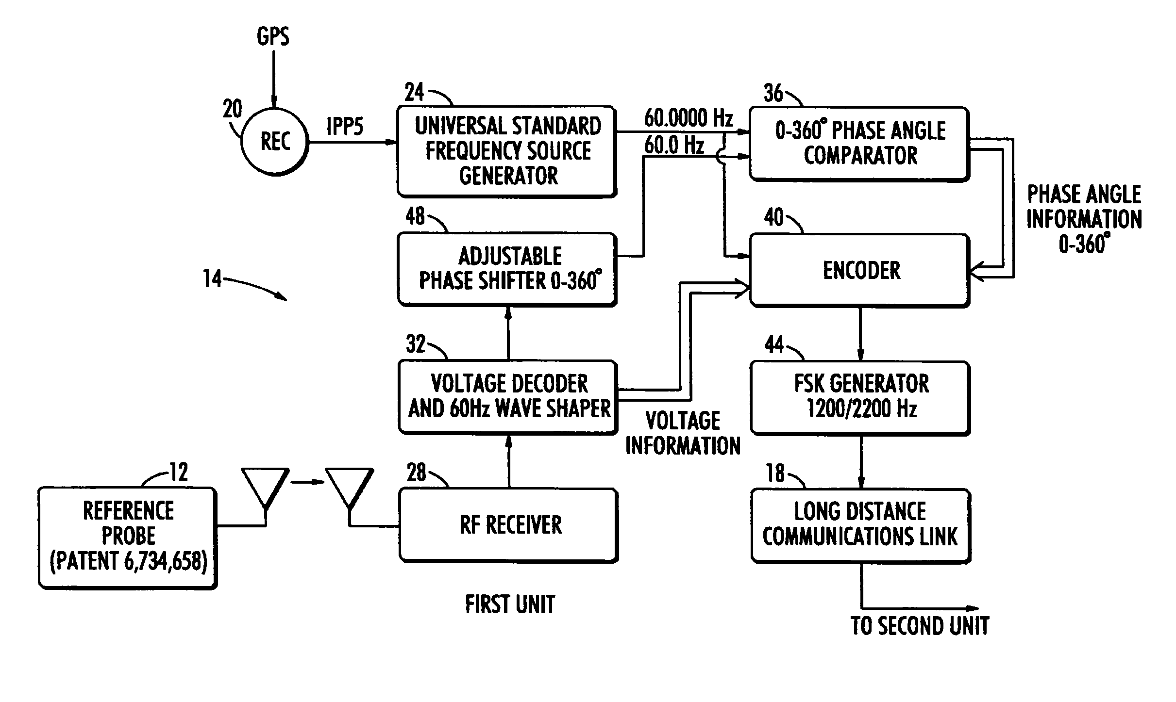
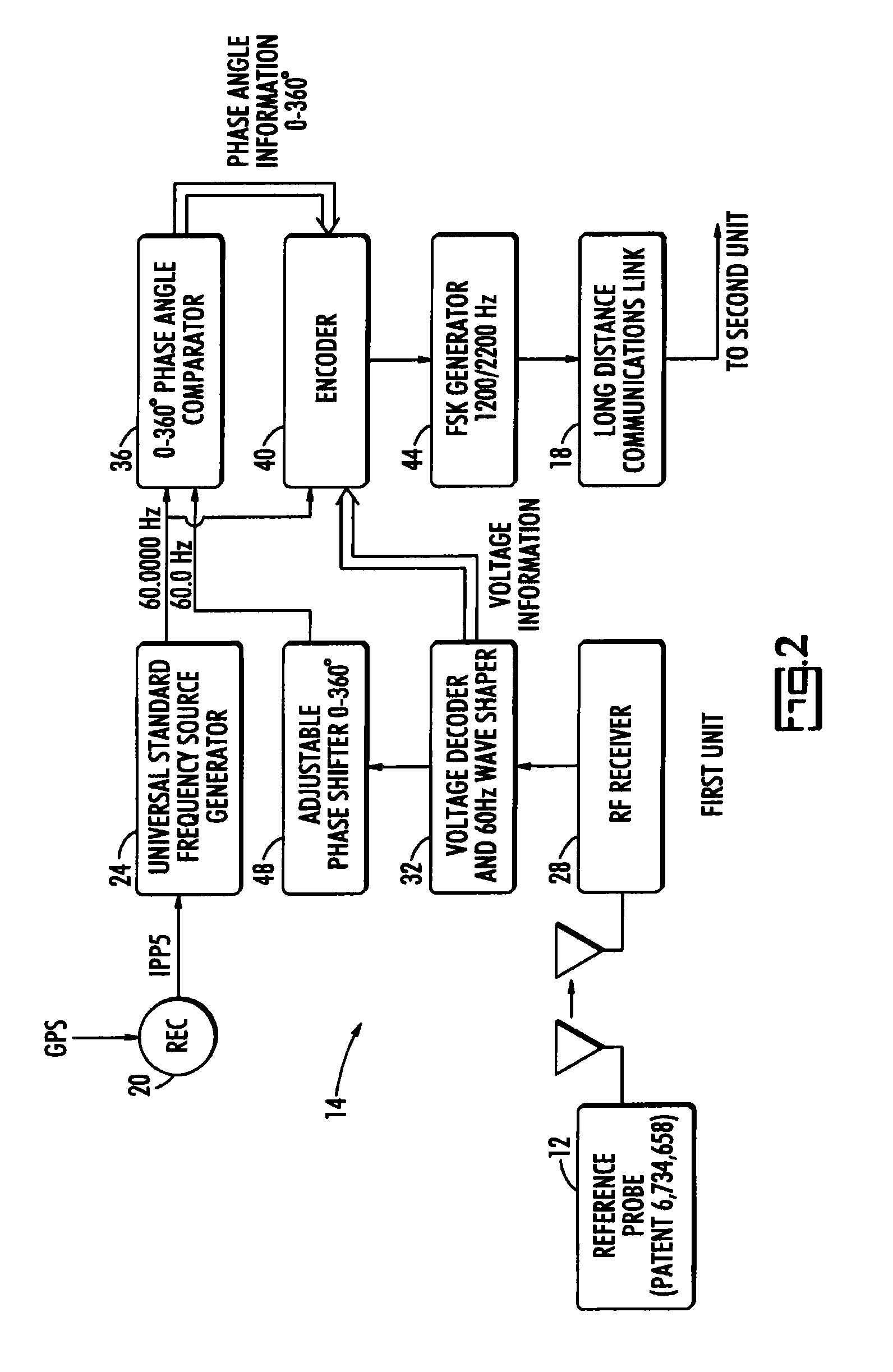
[0020]The present invention is a long range phasing voltmeter system that is an improvement over existing long range phasing voltmeter systems. The improvements lie in the system's ability to accurately determine multiple parameters of an electrical system, such as phase, phase angle, phase sequence, phase rotation, voltage and voltage difference, when the electrical conductors are separated by a distance that may be many miles.

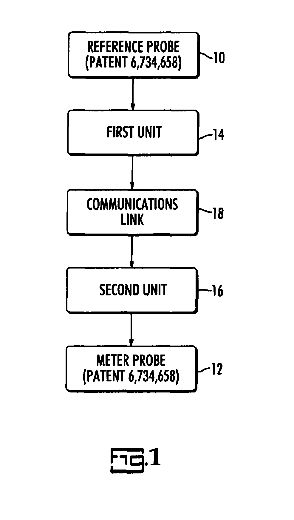
[0021]The present invention is preferably applied to the phasing voltmeter system disclosed and described in U.S. Pat. No. 6,734,658 that includes a master probe and a supplemental probe. The supplemental probe measures the time-varying voltage signal on the reference conductor; the master probe measures the time-varying voltage on the field conductor. The term supplemental probe in U.S. Pat. No. 6,734,658 is replaced herein with the term reference probe, which probe measures the voltage on an arbitrarily-designated reference conductor. The term master probe ...


PUM


Abstract

A long range wireless phasing voltmeter determines the phase difference between the time-varying voltage carried on a reference electrical conductor and another, field conductor. The voltage signal from the reference conductor is measured by a reference probe and compared by a first unit in communication with that reference probe to a precision 60 Hz signal generated from a GPS receiver. The phase difference between these, in the form of a nine-bit, audible signal using frequency shift keying to modulate the carrier frequency, is transmitted by the first unit to a second unit perhaps miles away. A receiver in the second unit decodes the signal and uses another precision 60 Hz signal generated from another GPS receiver to re-create a surrogate of the original reference voltage signal. This surrogate signal is forwarded to a meter probe that is measuring the signal on a field conductor. The meter probe can then compare the two signals to determine the phase angle difference between them.

Description

BACKGROUND OF THE INVENTION[0001]The present invention relates to high-voltage voltmeters in general and to long-range wireless phasing voltmeters in particular.[0002]Three-phase high-voltage distribution and transmission lines consist of three energized conductors and a fourth, neutral or “ground” conductor. The three energized conductors each carry an electrical voltage that varies in magnitude at the same frequency but the phase of the voltage carried by each conductor is displaced by a phase angle of 120 degrees. The conductors carrying these three different-phased voltages are generally labeled as the A, B, C or 1, 2, 3 conductors, or equivalent depending on the utility, to tell them apart. In the simplest arrangement, the first phase, or reference phase, is arbitrarily designated to be 0 degrees, making the next phase 120 degrees displaced from the first and the last phase 240 degrees displaced from the first.[0003]When two sets of high voltage distribution and transmission li...

Claims


Application Information

Patent Timeline
Patent Type & Authority Patents(United States)
IPC IPC(8): G01R19/00
CPCG01R25/00G01R29/18
Inventor BIERER, WALTER S.
Owner BIERER WALTER S
Why Eureka
Try Eureka