
Microprocessor shifter circuits utilizing butterfly and inverse butterfly routing circuits, and control circuits therefor

a microprocessor and shifter technology, applied in the field of computer system circuits, can solve the problems of reducing the amount of circuitry and chip space, limiting the flexibility and ease of implementation of existing microprocessor bit manipulation operations at the hardware level, and often limited to shift and rotate operations

Active Publication Date: 2012-10-09
THE TRUSTEES FOR PRINCETON UNIV
View PDF23 Cites 11 Cited by
  • Summary
  • Abstract
  • Description
  • Claims
  • Application Information

AI Technical Summary

Benefits of technology

[0010]The present invention relates to microprocessor shifter circuits utilizing butterfly and inverse butterfly circuits, and control circuits therefor. The shifter circuits can be implemented in existing microprocessors, and allow for complex bit manipulations to be performed by such microprocessors at high speeds. The shifter circuits can perform butterfly and inverse butterfly operations, parallel extract and parallel deposit operations, group operations, mix operations, bit permutation operations, as well as instructions executed by existing microprocessors. The shifter circuits can replace existing shifter circuits in microprocessors, so as to provide new ways for conducting existing shift, rotate, extract, deposit, and mix operations, as well as more advanced bit manipulation instructions. The shifter circuits can be implemented with a reduced amount of circuitry, thus conserving chip space. User applications relating to steganography, binary image morphology, transfer coding, bioinformatics, imaging, and integer compression techniques, among other applications, can be implemented using the shifter circuits of the present invention. The shifter circuits can be provided in various combinations to provide microprocessor functional units which perform a plurality of bit manipulation processes.

Problems solved by technology

Unfortunately, bit manipulation operations carried out by existing microprocessors are limited in terms of flexibility and ease of implementation at the hardware level.
For example, bit manipulation operations performed by existing microprocessors are often limited to shift and rotate operations.
Since a microprocessor is typically optimized around the processing of words (i.e., fixed-length groups of binary bits of information), it is not surprising that bit-level operations are not well-supported by current word-oriented microprocessors.
However, these operations are implemented by complex shifter functional unit circuitry, which appreciably adds to the size and complexity of the microprocessor.
While circuitry to achieve these operations can be built by assembling simple logical and shift operation circuits, or by implementing same in firmware, such approaches often result in very large circuits or slow execution speeds.

Method used


Image

  • Microprocessor shifter circuits utilizing butterfly and inverse butterfly routing circuits, and control circuits therefor
  • Microprocessor shifter circuits utilizing butterfly and inverse butterfly routing circuits, and control circuits therefor
  • Microprocessor shifter circuits utilizing butterfly and inverse butterfly routing circuits, and control circuits therefor

Examples


first embodiment

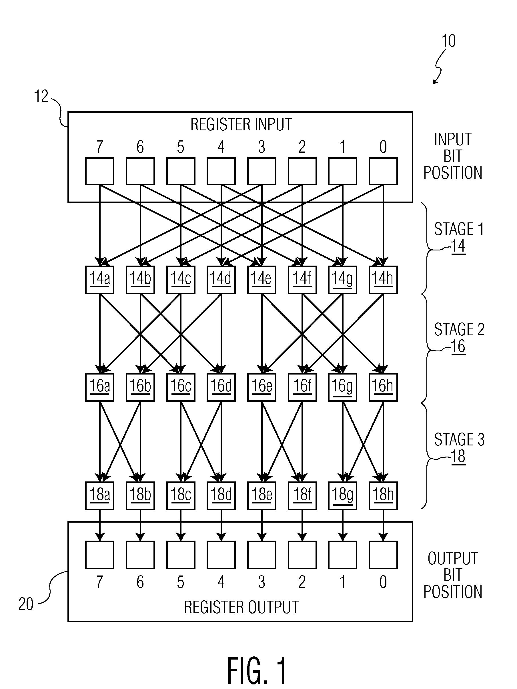
[0043]FIG. 1 is a diagram showing the shifter circuit 10 of the present invention. The shifter circuit 10 includes a register input 12, a first shifter stage 14, a second shifter stage 16, and a third shifter stage 18, and a register output 20. The shifter circuit 10 can replace shifter circuits of existing processors. By the term “processor,” it is meant a microprocessor (or other circuitry of existing microprocessors which perform bit operations, such as those discussed above) or any other type of processor, such as digital signal processors, embedded processors, cryptoprocessors, communications processors, System-On-Chip(s) (SOC), etc. The register input 12 and output 20 are showing having a width of 8 bits (i.e., bit positions 0 through 7), but it is to be understood that any desired bit widths could be accommodated. The circuit stages 14-18 and their associated interconnections form a butterfly circuit, wherein the first stage 14 includes multiplexers 14a-14h, the second stage ...

second embodiment

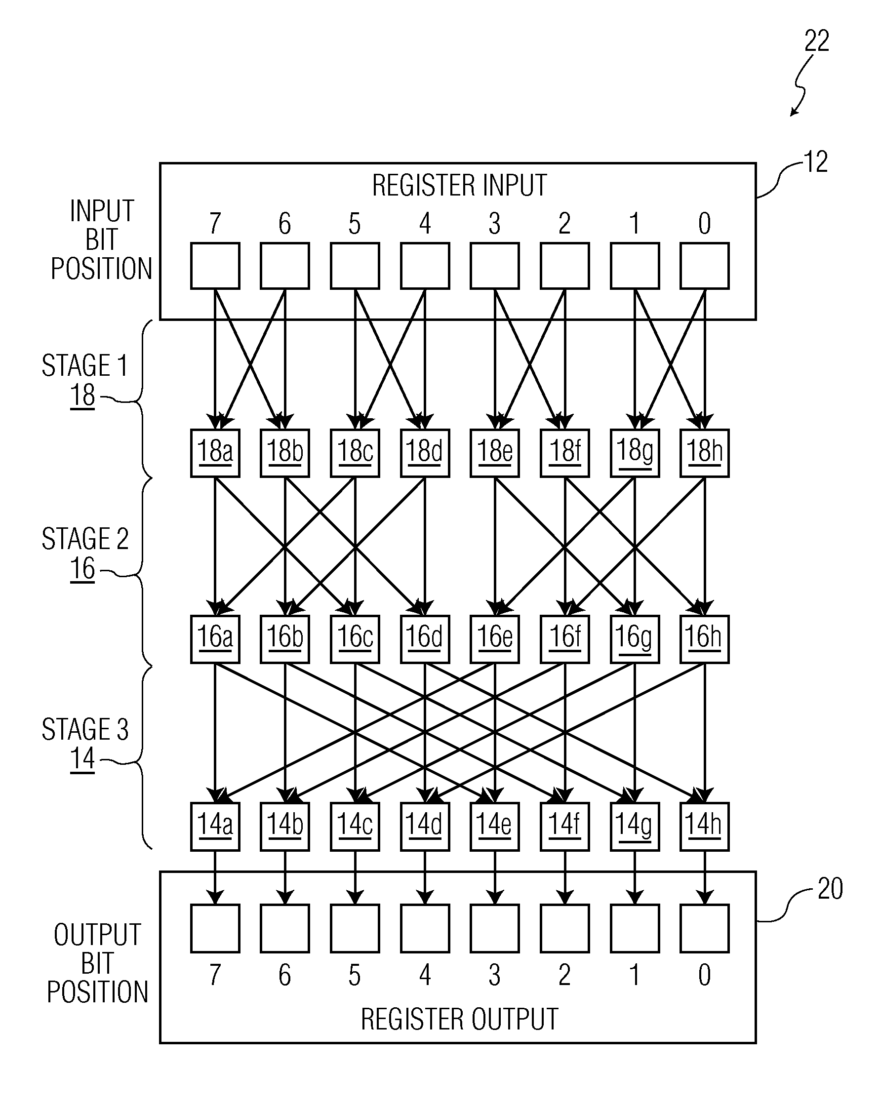
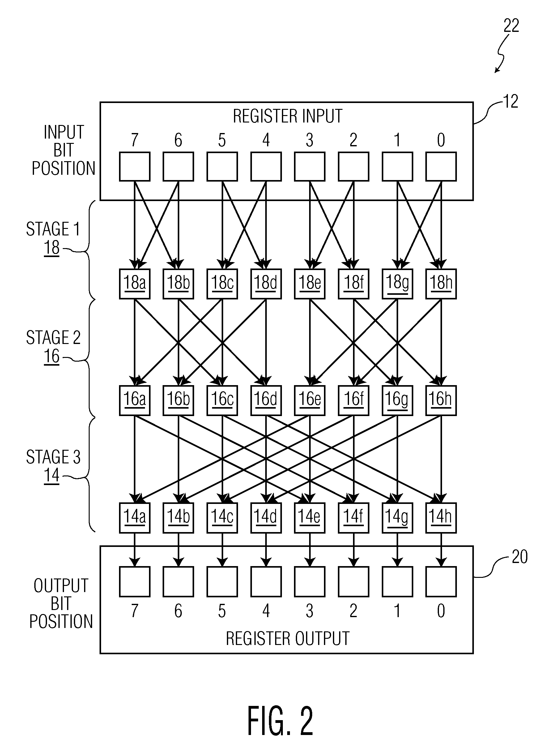
[0044]FIG. 2 is a diagram showing the shifter circuit of the present invention, indicated generally at 22, wherein an inverse butterfly configuration is shown. As can be seen, the circuit stages 14-18 and their associated interconnections are reversed, such that the circuit stage 18 is provided as the first circuit stage and is connected to the register input 12, and the circuit stage 14 is provided as the third circuit stage and is interconnected to the register output 20. The circuit stage 16 remains the second circuit stage, interconnected between the first and third circuit stages 18 and 14. As mentioned above, the shifter circuit 22 can replace shifter circuits of existing microprocessors (or other circuitry of existing microprocessors which perform bit operations, such as those discussed above), and any desired bit width could be provided.

[0045]The shifter circuits 10 and 22 could be implemented in a microprocessor individually, or they could be connected to each other to form...


PUM


Abstract

Microprocessor shifter circuits utilizing butterfly and inverse butterfly circuits, and control circuits therefor, are provided. The same shifter circuits can also perform complex bit manipulations at high speeds, including butterfly and inverse butterfly operations, parallel extract and deposit operations, group operations, mix operations, permutation operations, as well as instructions executed by existing microprocessors, including shift right, shift left, rotate, extract, deposit and multimedia mix operations. The shifter circuits can be provided in various combinations to provide microprocessor functional units which perform a plurality of bit manipulation operations.

Description

RELATED APPLICATIONS[0001]The present application claims the priority of U.S. Provisional Application Ser. No. 60 / 931,493 filed May 23, 2007, the entire disclosure of which is expressly incorporated herein by reference.STATEMENT OF GOVERNMENT INTERESTS[0002]The present invention was made with government support under Department of Defense Grant No. H98230-04-C-0496. Accordingly, the Government has certain rights to the present invention.BACKGROUND OF THE INVENTION[0003]1. Field of the Invention[0004]The present invention relates to circuitry for computer systems, and more specifically, to microprocessor shifter circuits utilizing butterfly and inverse butterfly circuits, and control circuits therefor.[0005]2. Related Art[0006]Bit manipulation operations are important features of modern microprocessors. Unfortunately, bit manipulation operations carried out by existing microprocessors are limited in terms of flexibility and ease of implementation at the hardware level. For example, b...

Claims


Application Information

Patent Timeline
Patent Type & Authority Patents(United States)
IPC IPC(8): G06F5/01
CPCG06F7/762G06F5/01G06F9/30018G06F9/30032G06F9/3004
Inventor LEE, RUBY B.HILEWITZ, YEDIDYA
Owner THE TRUSTEES FOR PRINCETON UNIV
Learn More