Low stress traction system

Active Publication Date: 2012-10-16
SCHLUMBERGER TECH CORP
View PDF19 Cites 19 Cited by
  • Summary
  • Abstract
  • Description
  • Claims
  • Application Information

AI Technical Summary

Benefits of technology

[0004]In general, the present invention provides a system and method for providing traction against an anchoring surface of a well component without creating high stress concentrations that weaken the well component. An anchoring device comprises anchoring members that are movable between a contracte

Problems solved by technology

However, use of such devices tends to weaken the well casing by creating high stress concentrations where the well casing is deformed with the s

Method used


Image

  • Low stress traction system
  • Low stress traction system
  • Low stress traction system

Examples


Example

[0016]In the following description, numerous details are set forth to provide an understanding of the present invention. However, it will be understood by those of ordinary skill in the art that the present invention may be practiced without these details and that numerous variations or modifications from the described embodiments may be possible.

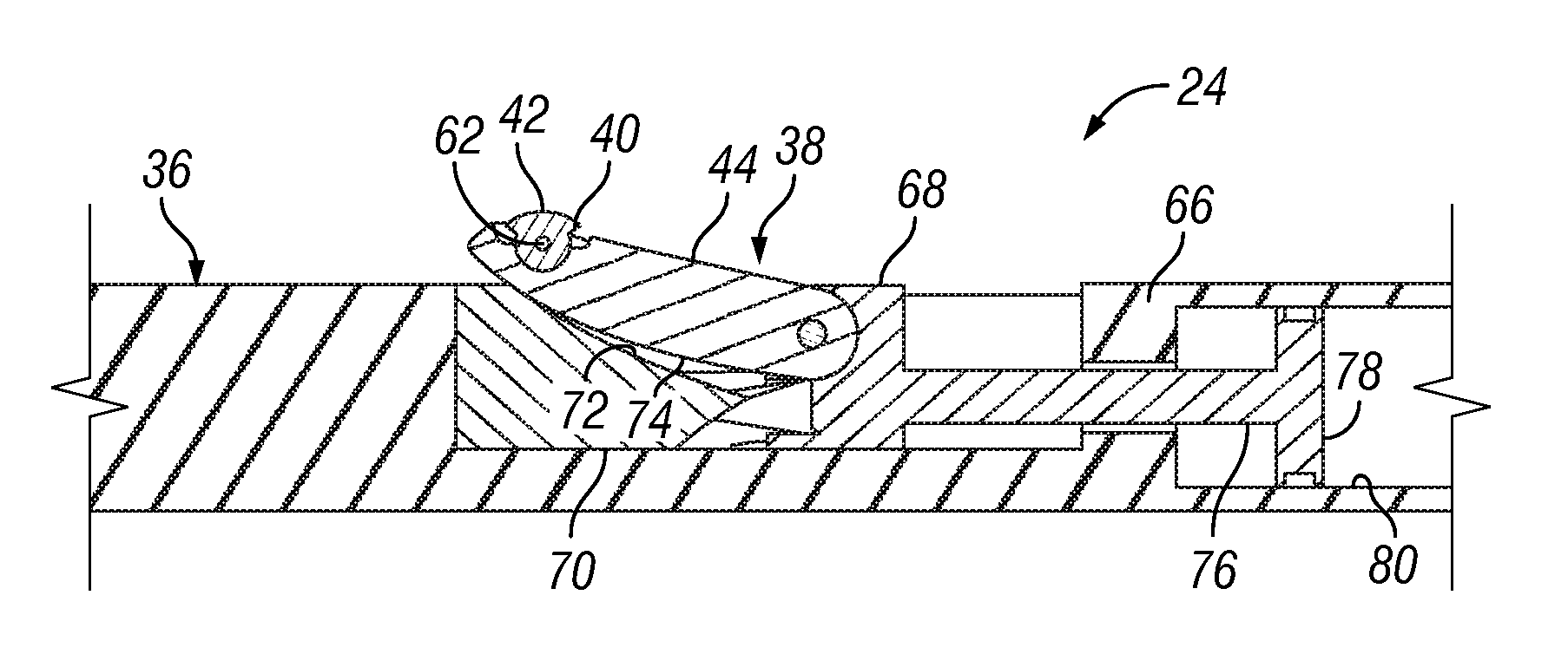
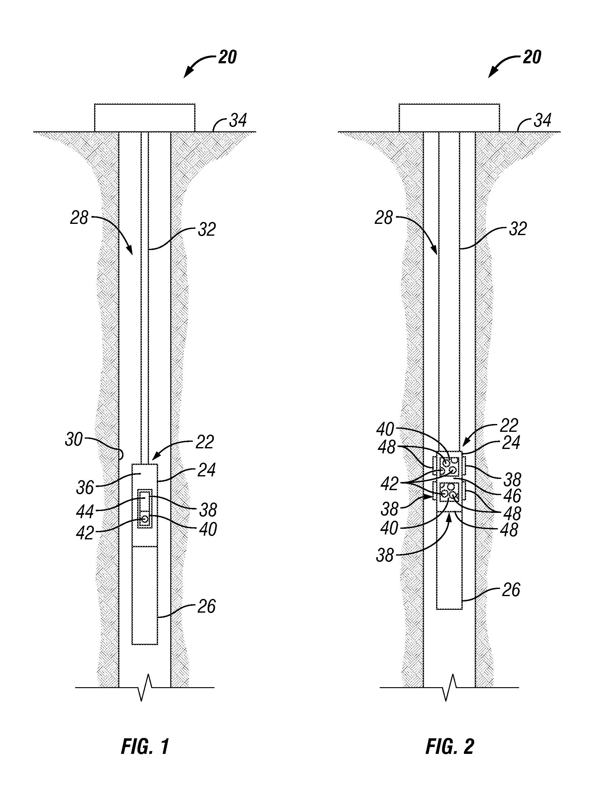
[0017]The present invention generally relates to a system and method for anchoring a tool in a wellbore. The system and methodology utilize a device for supporting a large traction force at the surface of a component, e.g. an inner surface of a well tubular, with which the device is in contact. The device is able to provide a very large level of traction per unit of contact area, while minimizing the detrimental effect on the strength and corrosion resistance of the component with which it is in contact.

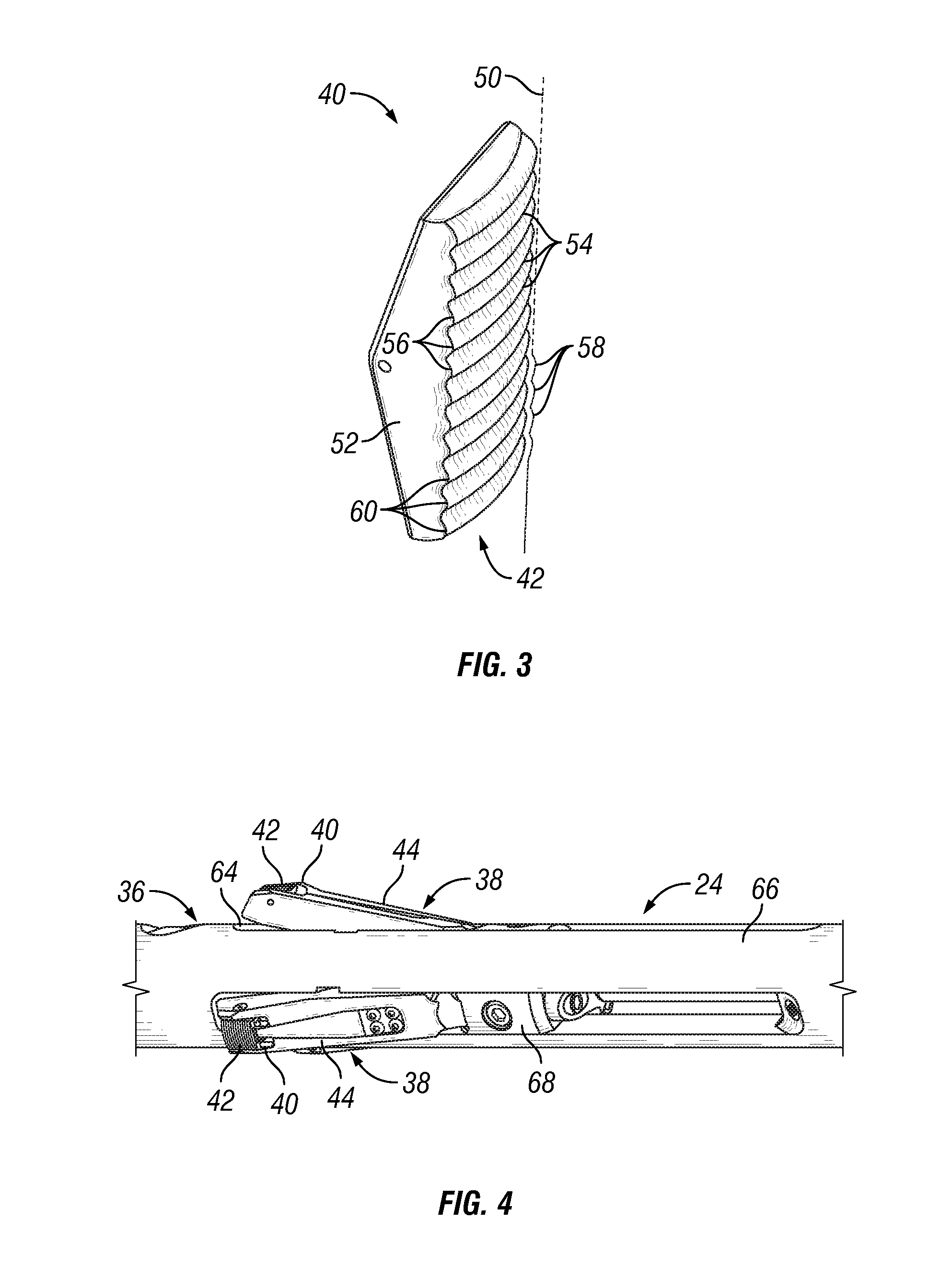
[0018]In one embodiment, the device comprises one or more traction surfaces having protruding traction features designed to press into an a...


PUM


Abstract

A technique enables anchoring of a tool in a wellbore. The technique provides traction against a well component without creating high stress concentrations that weaken the well component. An anchoring device comprises anchoring members that are selectively movable to an expanded configuration for anchoring the tool. The anchoring members have traction surfaces able to selectively engage a smooth anchoring surface of the well component at any desired location along the well component. Each traction surface is formed to facilitate traction while minimizing stress concentration.

Description

CROSS-REFERENCE TO RELATED APPLICATION[0001]The present document is based on and claims priority to U.S. Provisional Application Ser. No. 60 / 973,596, filed Sep. 19, 2007.BACKGROUND[0002]Many types of well related operations rely on traction in a wellbore to secure a device at a desired position during the well related operation. One method of establishing traction is through static friction. Mating materials are selected which tend to have large coefficients of friction when mated together. An example of a device that employs static friction to support a large force is a slat-reinforced inflatable packer. A slat-reinforced inflatable packer is constructed with an inner, inflatable element covered by metal reinforcing slats. When the inner element is inflated, the metal slats are pressed against an inside surface of a pipe in which the packer is installed. Friction between the slats and the pipe provides the traction required to secure the packer.[0003]In other well applications, pac...

Claims


Application Information

Patent Timeline
IPC IPC(8): E21B23/00
CPCE21B33/129E21B23/01
Inventor MARTINEZ, RUBENSPENCER, MAX E.
Owner SCHLUMBERGER TECH CORP
Why Eureka
Try Eureka