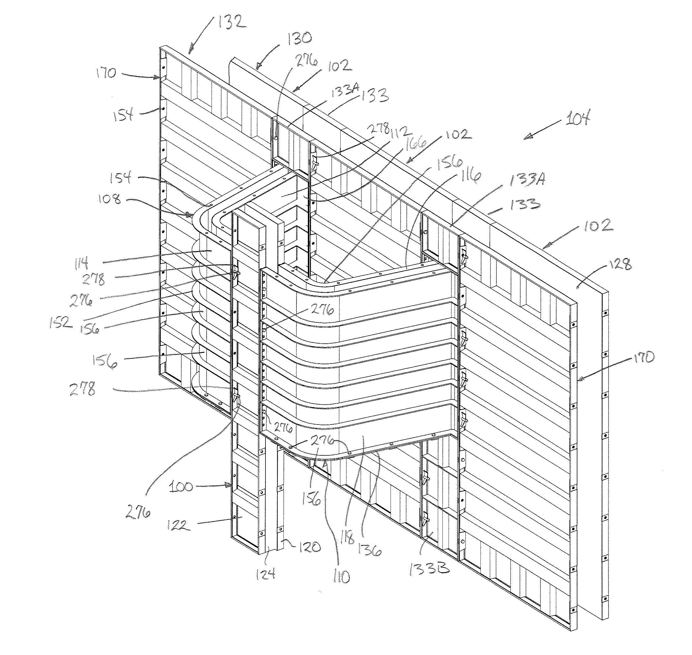
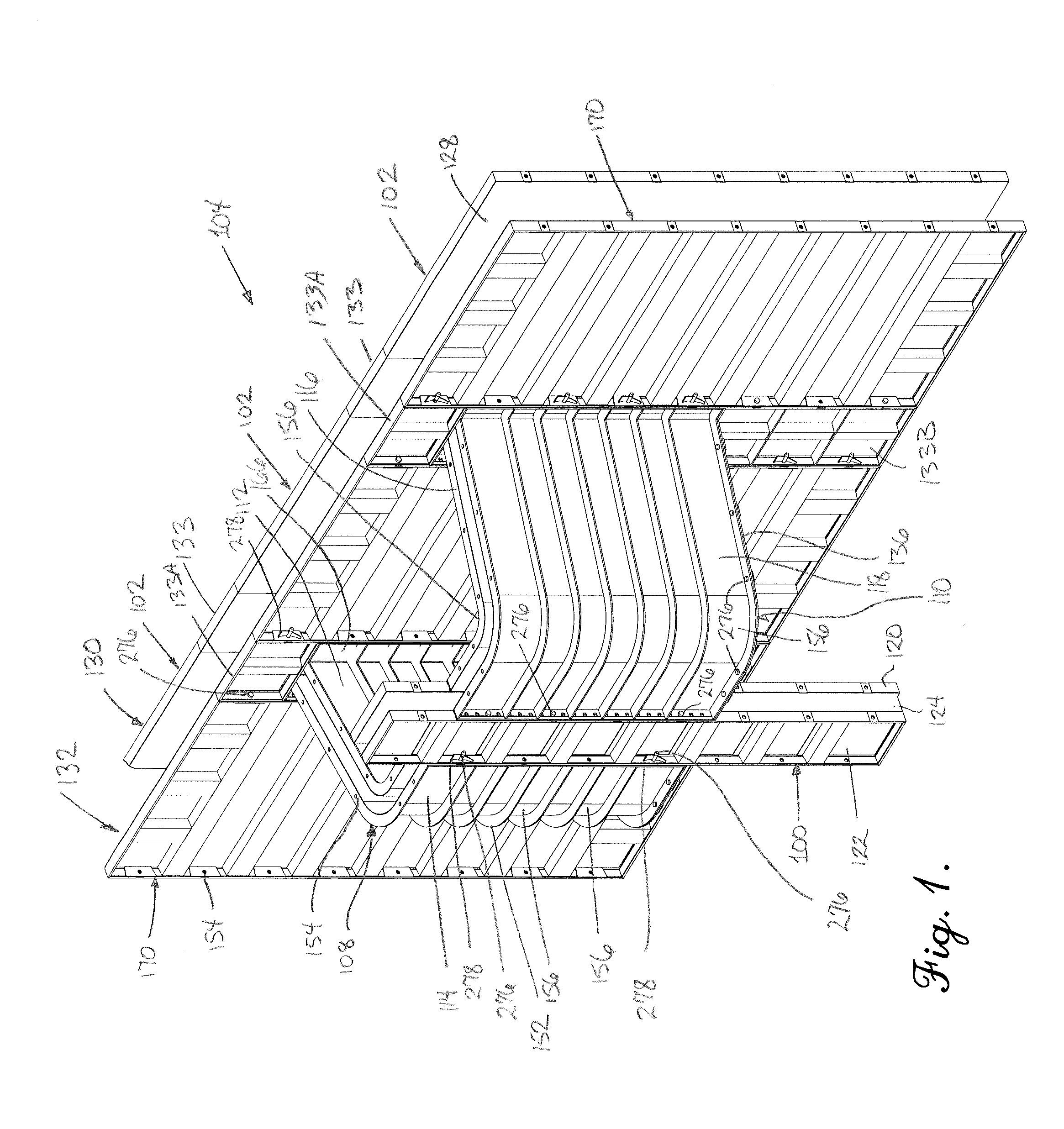
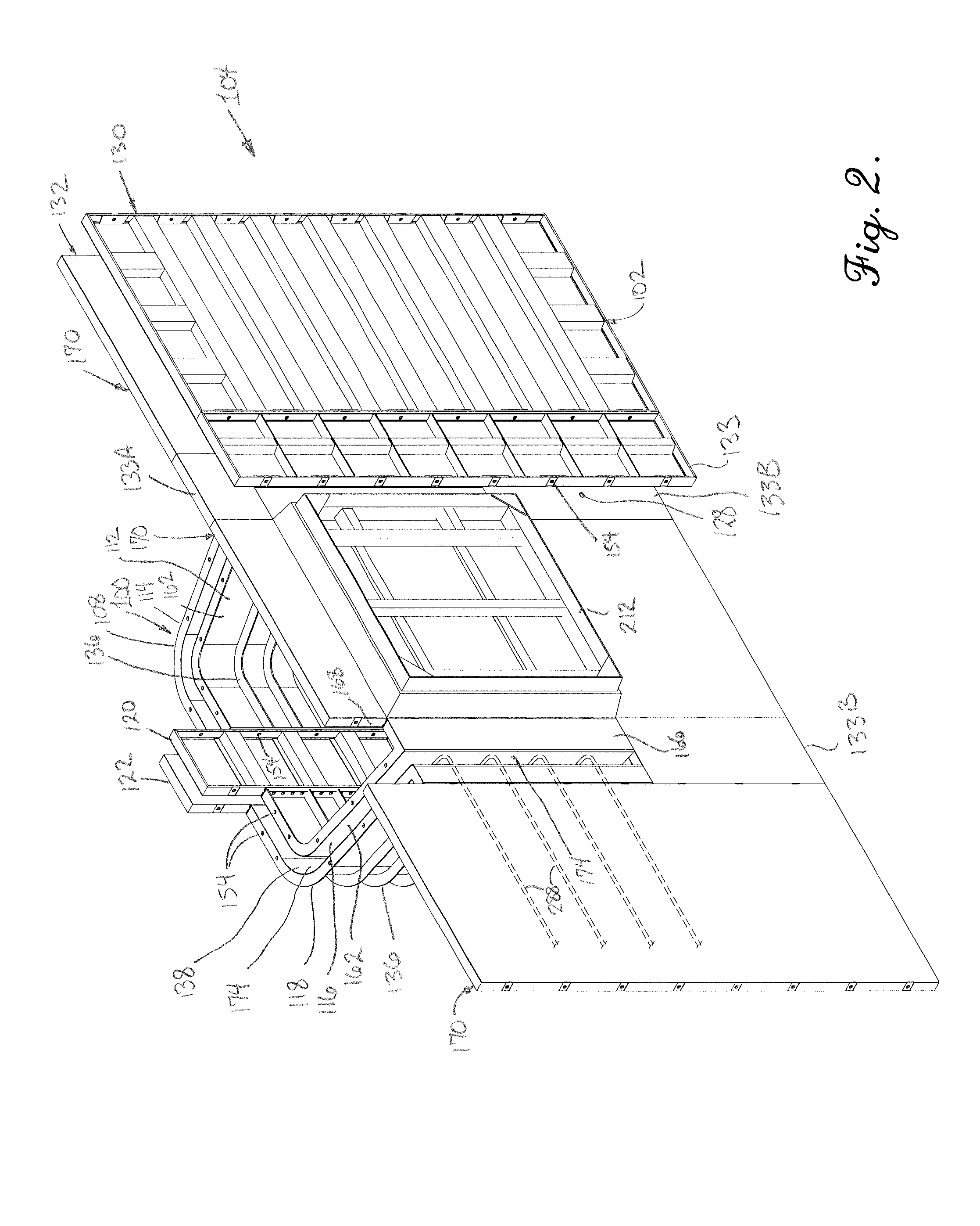
[0010]These and other advantages have largely been achieved by the apparatus and method for forming cast-in-place window wells of the present invention. While forming systems of wood or
metal forms are well known, the present invention provides an easy and economical approach to the problems associated with window well construction not previously contemplated nor developed in the prior art. As a result, a window well forming
system has been developed which provides not only an economical way of forming window wells at the job site which integrates in structure and appearance with the foundation walls, reduces the inventory issues of the contractor, and provides enhanced flexibility in the size of the window well and consequently the
window opening, but also results in enhanced strength to the foundation wall as compared to existing window well approaches.
[0011]Broadly speaking, the present invention achieves these objects by providing forming panel modules which integrate with existing forming panels to provide a channel for forming a window well. The forming panel modules are configured to provide an attractive and correctly sized window well and to
mount with conventional
metal forms as a part of a forming wall
system. The concrete window well forming panel systems utilizes the forming panel modules which are positioned opposite a portion of the forming wall
system for the foundation wall and which provides the
window opening so that concrete poured between the forms flows into the window well apparatus and integrates with the existing wall. The forming panel modules are preferably provided as pairs of module sections, typically configured as inner and outer sections, whereby a bottom rail of the modules is elevated relative to the bottom rail of the foundation wall forming panel modules. Most preferably, each section is a separate forming member which may be connected directly or indirectly to forming panels for the foundation wall, and preferably have an inboard leg which extends outwardly from the forming panels for the exterior of the foundation wall, and outboard legs which are angled with respect to the inboard leg to extend toward the outboard legs of the other module and provide a continuous concrete-receiving channel for defining the window well wall. Because the modules for forming the window well walls are in pairs, and thus separate module pairs are provided for the right and left side of the window well wall with a rail which permits them to be connected or separate, the modules permit selective adjustment of the width of the window well from a minimum width to a wider width, the minimum width being defined by the size and configuration of the inner and outer sections of the modules. In order to increase the width of the window well to be formed from a minimum width, and to provide a
pier for the window well, one or several inner and outer filler forms may be positioned between the angular forming members. Preferably, the outboard legs of the module are oriented substantially parallel to the forming panels for the foundation wall, while the inboard legs are oriented at an
oblique angle relative to the outboard leg and to the adjacent feet which are aligned with the forming panels of the foundation wall. An arcuate, rounded corner preferably connects the inboard leg to the outboard leg to minimize stress concentrations in the concrete window well wall formed thereby.
[0012]Advantageously, the forming panel modules are configured to accept like-configured modules atop one another, to increase the height of the window well formed thereby. Furthermore, filler panels may be inserted between the modules and the panels which form the structure wall to increase the thickness of the wall as constructed. Where desired, the forming panel modules may be constructed so as to form or receive steps to aid in ingress or egress from the window well.
[0013]Because the forming panel modules are configured to couple to and integrate with existing flat forming panels, and provide the flexibility to expand in depth, height, length and wall thickness, the inventory of the contractor is greatly reduced. In especially preferred embodiments, the modules are configured with identically shaped inner and outer sections, whereby inversion of an inner section of one module, e.g. an inner section or an outer section of a left module, will then serve as a corresponding inner or outer section of the other module, e.g. the right module. Because the resulting window well wall is integrated into the foundation wall because it is poured in place therewith, the window well wall adds dimensional strength and reinforces the wall of the foundation surrounding the window. Similarly, because in the preferred embodiments, the window well wall does not extend downwardly as far as the adjacent foundation wall and its bottom edge is elevated above the bottom of the foundation wall which is adjacent to the window well, the aforementioned problems and additional costs including those attendant to excavation, labor, and excess material are avoided. When needed, the ability to pour a
pier contemporaneously with the window well avoids a cantilevered stress on the foundation wall.
[0015]In another alternative embodiment, the inboard leg of one or both of the inner sections and the outboard sections may be pivotally coupled to an adjacent foot which is configured for
coupling and mounting to an adjacent forming panel by hinges. The use of a hinge
coupling between the feet and the inboard legs facilitates installation of forming panels to the window well forming system, and provides an ability to adjust for variations in form placement or site conditions.
[0016]The present invention thus provides for an
improved method of constructing structures having window openings and utilizing window wells. By providing complementally configured inner and outer sections and
coupling the inner and outer sections which are coupled to forming panels
proximate a window buck, a window well may be cast in place by depositing flowable concrete between the inner and outer sections. Upon removal of the window well forming system, the resulting window well is of monolithic construction as a part of the wall, such as a foundation wall, of the structure. As used herein, “monolithic” construction means that the resulting window well wall and the building wall, typically a foundation wall of a building structure, is formed by concrete which is continuous and unbroken therebetween when cured. Most preferably, the monolithic construction of the present invention includes the provision of reinforcing steel in the form of bars, mesh or the like which extends outwardly from the building wall and extends into the window well wall, such that the concrete is poured to flow from the channel between the opposing forming panels of the wall and into the channel between the opposing panels of the window well module such that the poured concrete of the building wall and the window well wall cures at the same time and is continuous. Most preferably, at least that part of the window well wall formed by the angular inner and outer sections does not extend downwardly to be on substantially a common horizontal plane with the bottom of the foundation wall reducing waste. This can be accomplished by grading below the window well forming system hereof, or more preferably, by utilizing base plates which prevent the flow of concrete downwardly out from the channel between the forming panels. When additional support is needed for a window well, the present invention also provides for a pier to be poured as a part of the window well wall and on the outboard portion of the window well wall.


