Metal gasket

a metal gasket and metal technology, applied in the direction of engine sealing, machine/engine sealing, etc., can solve the problems of affecting the sealing performance of the metal gasket, and the stress created in each individual sealing part which has been separated from the adjoining sealing parts to be reduced, so as to minimize the concentration of stress in the metal gask

Inactive Publication Date: 2016-08-04
JAPAN METAL GASKET CO LTD
View PDF20 Cites 7 Cited by
  • Summary
  • Abstract
  • Description
  • Claims
  • Application Information

AI Technical Summary

Benefits of technology

[0005]In view of such a problem of the prior art, a primary object of the present invention is to provide a metal gasket that can minimize localized concentration of stress.

Problems solved by technology

As the metal gasket thermally expands under a high temperature condition, if the two parts that interpose the metal gasket therebetween have different thermal expansion coefficients from that of the metal gasket, a stress is created in the metal gasket to such an extent that the resulting deformation may impair the sealing performance of the metal gasket.
However, the metal gasket disclosed in JPS62-167812U does not allow the stress created in each individual sealing part which has been separated from the adjoining sealing parts to be reduced.
As a result, each sealing part, in particular a bead thereof, could be distorted and / or fractured, and the designed sealing performance may not be maintained.

Method used


Image

  • Metal gasket
  • Metal gasket
  • Metal gasket

Examples


Embodiment Construction

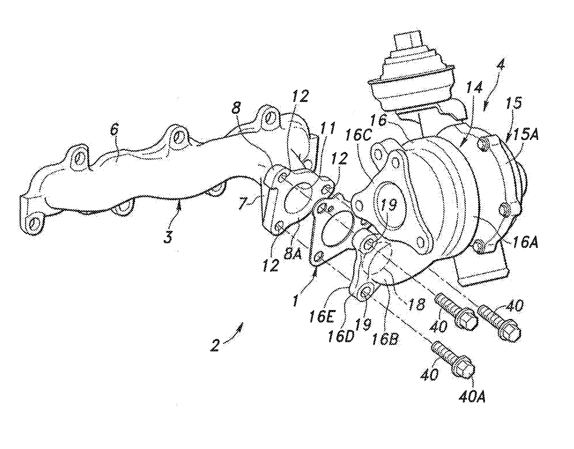
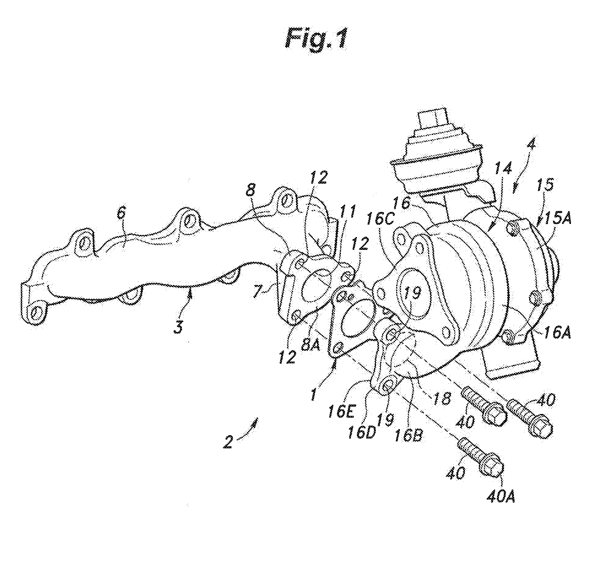
[0023]An embodiment of the metal gasket of the present invention as applied to the exhaust system of an internal combustion engine is described in the following with reference to the appended drawings.

[0024]As shown in FIG. 1, the metal gasket of the illustrated embodiment is used in an exhaust system 2 of an internal combustion engine. The exhaust system 2 comprises an exhaust manifold 3 connected to a cylinder head of the engine and a turbocharger 4 connected to the downstream end of the exhaust manifold 3.

[0025]The exhaust manifold 3 includes a branch pipe portion 6 communicating with the exhaust ports formed in the cylinder head and a merging portion 7 provided at the downstream end of the branch pipe portion 6 in which individual pipes forming the branch pipe portion 6 merge into one passage. The downstream end of the merging portion 7 is formed with a manifold side flange 8 extending radially outward. The end surface of the manifold-side flange 8 defines a manifold-side fasten...


PUM


Abstract

Localized stress concentration is minimized in a metal gasket (1). The metal gasket (1) is configured to be interposed between fastening surfaces (8A, 16E) of component parts (3, 4), and comprises a passage hole (34) corresponding to a passage (11, 18) of the component parts opening out on the fastening surfaces, a bead (38) surrounding the passage hole in an endless manner, at least three bolt holes (35) formed outside of the bead to allow fastening bolts (40) for fastening the component parts to each other to be passed therethrough, a bolt pressure receiving region (41) being defined around each bolt hole so as to correspond to a head (40A) of the corresponding fastening bolt, a first region (42) being defined by linearly connecting the bolt pressure receiving regions of two adjoining bolt holes each other and being provided with a width equal to a diameter of the bolt pressure receiving regions, and a second region being defined as a part of the first region (42) located outside of the bead; and a through hole (36) formed in the second region (43).

Description

TECHNICAL FIELD[0001]The present invention relates to a metal gasket that can be used in high temperature applications,BACKGROUND ART[0002]Conventionally, the metal gasket has been used as a sealing structure for fastening surfaces or mating surfaces between a cylinder block and a cylinder head, and between a cylinder head and an exhaust manifold of an engine which are placed under high temperature conditions.[0003]As the metal gasket thermally expands under a high temperature condition, if the two parts that interpose the metal gasket therebetween have different thermal expansion coefficients from that of the metal gasket, a stress is created in the metal gasket to such an extent that the resulting deformation may impair the sealing performance of the metal gasket. To overcome this problem, with respect to a metal gasket interposed between a cylinder head and an exhaust manifold, a proposal was made to form a through hole in each of the connecting parts positioned. between the seal...

Claims


Application Information

Patent Timeline
Patent Type & Authority Applications(United States)
IPC IPC(8): F16J15/08F02F11/00
CPCF02F11/002F16J15/0831F16J15/0818F16J15/0825F02F11/00
Inventor YAMAZAKI, TAKAHIROTABUCHI, TAROUSHIMIZU, ATSUSHINAGANO, ISAOKOBAYASHI, NOBUHIDEJYUMONJI, HIDETAKA
Owner JAPAN METAL GASKET CO LTD
Why Eureka
Try Eureka