
Tools and methods for hanging and/or expanding liner strings

a technology of liner strings and tools, which is applied in the direction of survey, borehole/well accessories, construction, etc., can solve the problem of not providing a fluid seal between the liner and the casing, and achieve the effect of increasing the fluid pressur

Active Publication Date: 2012-10-16
WEATHERFORD TECH HLDG LLC
View PDF54 Cites 50 Cited by
  • Summary
  • Abstract
  • Description
  • Claims
  • Application Information

AI Technical Summary

Problems solved by technology

However, it does not provide a fluid seal between the liner and the casing.

Method used


Image

  • Tools and methods for hanging and/or expanding liner strings
  • Tools and methods for hanging and/or expanding liner strings
  • Tools and methods for hanging and/or expanding liner strings

Examples


Embodiment Construction

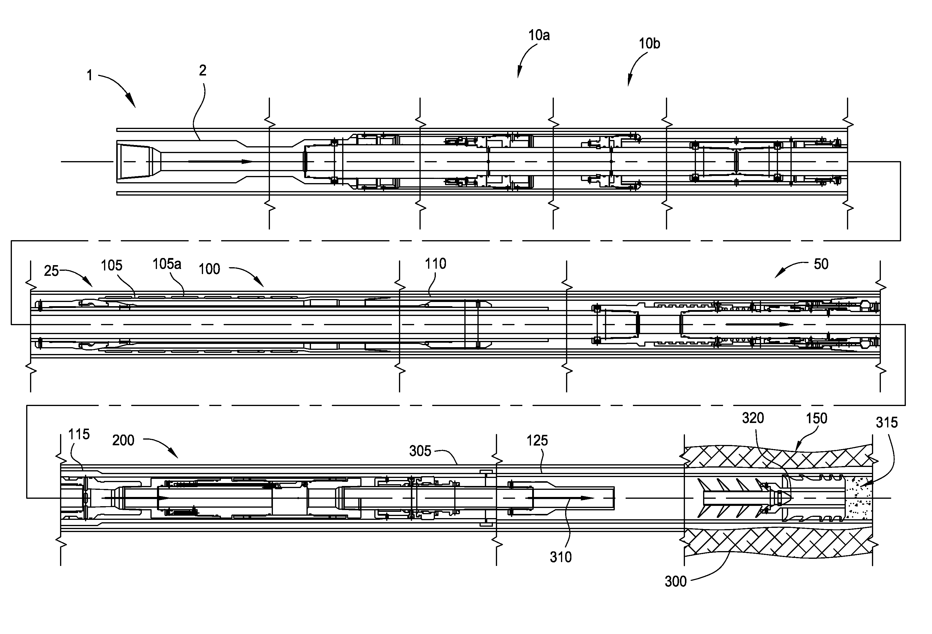
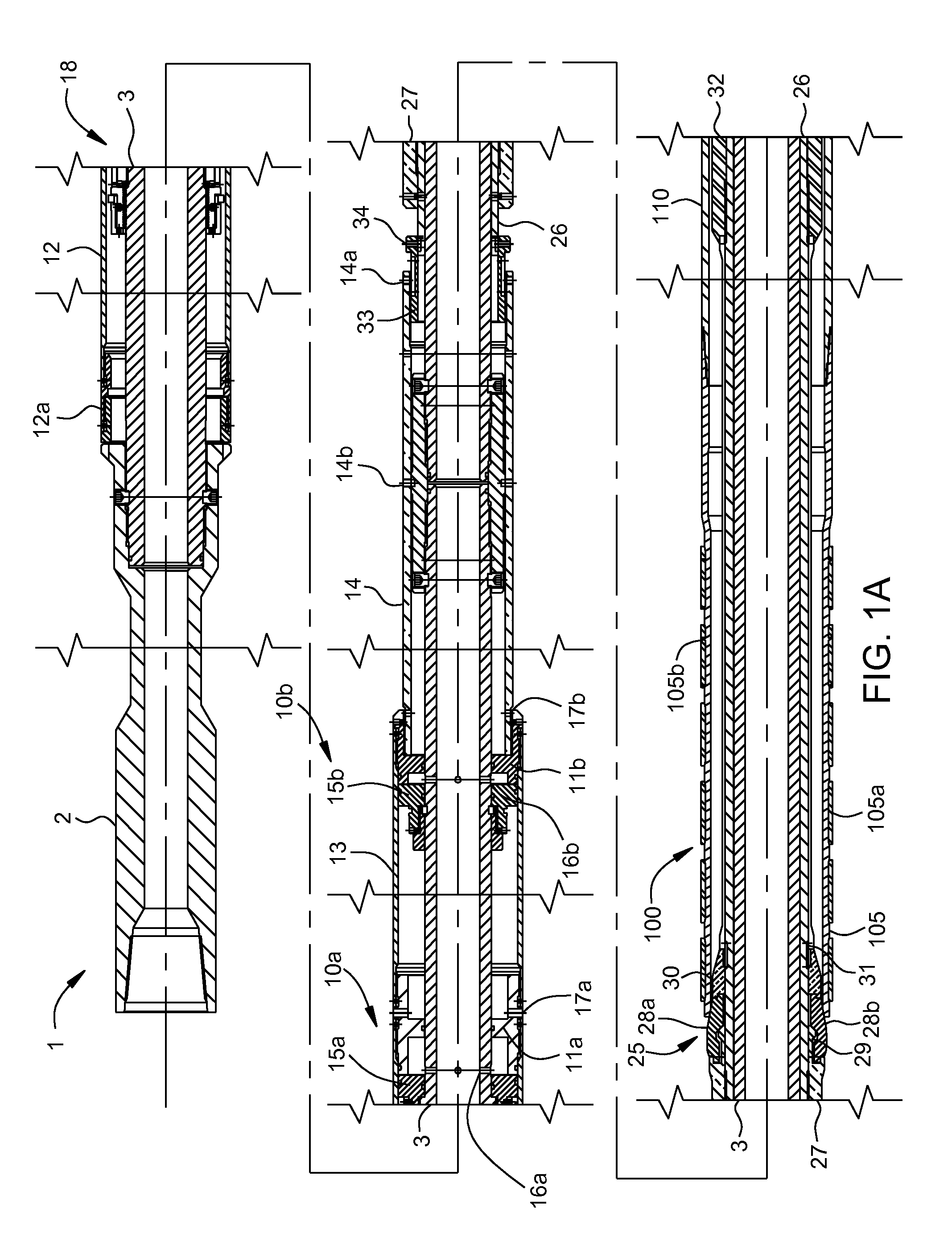
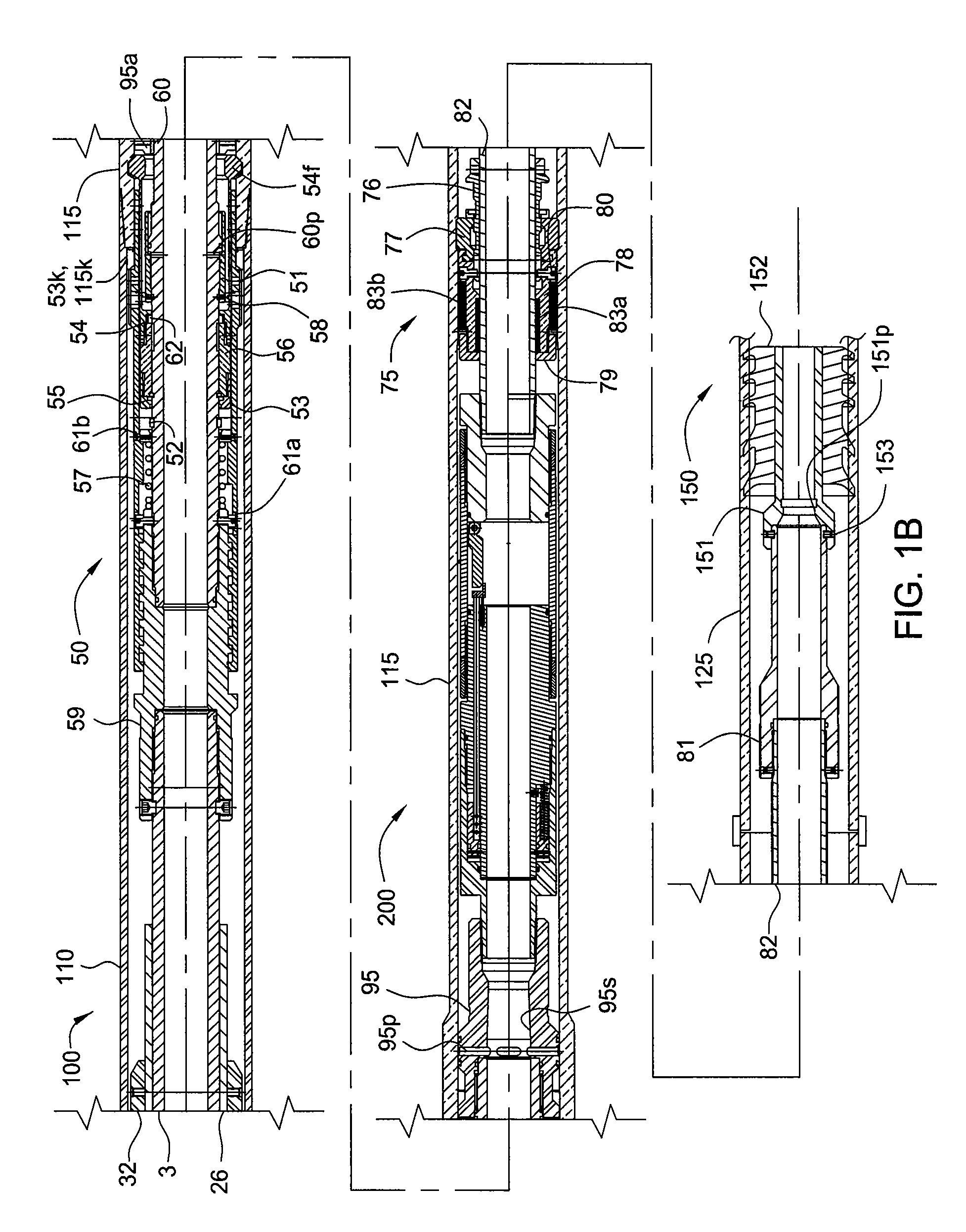
[0032]FIGS. 1A and 1B are cross-sections of a setting tool 1, a liner assembly 100, and a wiper assembly 150, according to one embodiment of the present invention. The setting tool 1, liner assembly 100, and wiper assembly 150 may be run into a wellbore using a run-in string 685 (see FIG. 6). The run-in string 685 may include a string of tubulars, such as drill pipe, longitudinally and rotationally coupled by threaded connections. The liner assembly 100 may include an expandable liner hanger 105, a polished bore receptacle (PBR) 110, one or more adapters 115, and a liner string 125. The setting tool 1 may be operable to radially and plastically expand the liner hanger 105 into engagement with a casing or liner string 305 (see FIG. 3A) previously installed in the wellbore. Non-sealing members of the setting tool 1 and liner assembly 100 may be made from a metal or alloy, such as steel or stainless steel. Alternatively, the PBR 110 may be disposed between the liner hanger and the run-...


PUM


Abstract

Embodiments of the invention generally relate to tools and methods for hanging and / or expanding liner strings. In one embodiment, a method of hanging a liner assembly from a previously installed tubular in a wellbore includes running the liner assembly and a setting tool into the wellbore using a run-in string. The setting tool includes an isolation valve and the liner assembly includes a liner hanger and a liner string. The method further includes sending an instruction signal from the surface to the isolation valve, wherein the isolation valve closes in response to the instruction signal and isolates a setting pressure in the setting tool from the liner string; and increasing fluid pressure in the setting tool, thereby setting the liner hanger.

Description

CROSS-REFERENCE TO RELATED APPLICATIONS[0001]This application claims benefit of U.S. Provisional Application Ser. No. 61 / 050,511, filed May 5, 2008, which is hereby incorporated by reference in its entirety.BACKGROUND OF THE INVENTION[0002]1. Field of the Invention[0003]Embodiments of the present invention generally relate to tools and methods for hanging and / or expanding liner strings.[0004]2. Description of the Related Art[0005]In wellbore construction and completion operations, a wellbore is initially formed to access hydrocarbon-bearing formations (i.e., crude oil and / or natural gas) by the use of drilling. Drilling is accomplished by utilizing a drill bit that is mounted on the end of a drill support member, commonly known as a drill string. To drill within the wellbore to a predetermined depth, the drill string is often rotated by a top drive or rotary table on a surface platform or rig, or by a downhole motor mounted towards the lower end of the drill string. After drilling t...

Claims


Application Information

Patent Timeline
Patent Type & Authority Patents(United States)
IPC IPC(8): E21B23/00E21B23/04E21B33/13
CPCE21B47/122E21B21/103E21B23/00E21B23/02E21B29/06E21B7/068E21B31/113E21B31/12E21B43/108E21B47/09E21B47/12E21B31/107E21B47/13
Inventor GIROUX, RICHARD L.LYNCH, MICHAELRING, LEV
Owner WEATHERFORD TECH HLDG LLC
Learn More