Semiconductor package and method for making the same
a technology of semiconductors and components, applied in the direction of electrical apparatus construction details, instruments, casings/cabinets/drawers, etc., can solve the problem of high yield rate, and achieve the effect of high yield rate and precise alignmen
- Summary
- Abstract
- Description
- Claims
- Application Information
AI Technical Summary
Benefits of technology
Problems solved by technology
Method used
Image
Examples
first embodiment
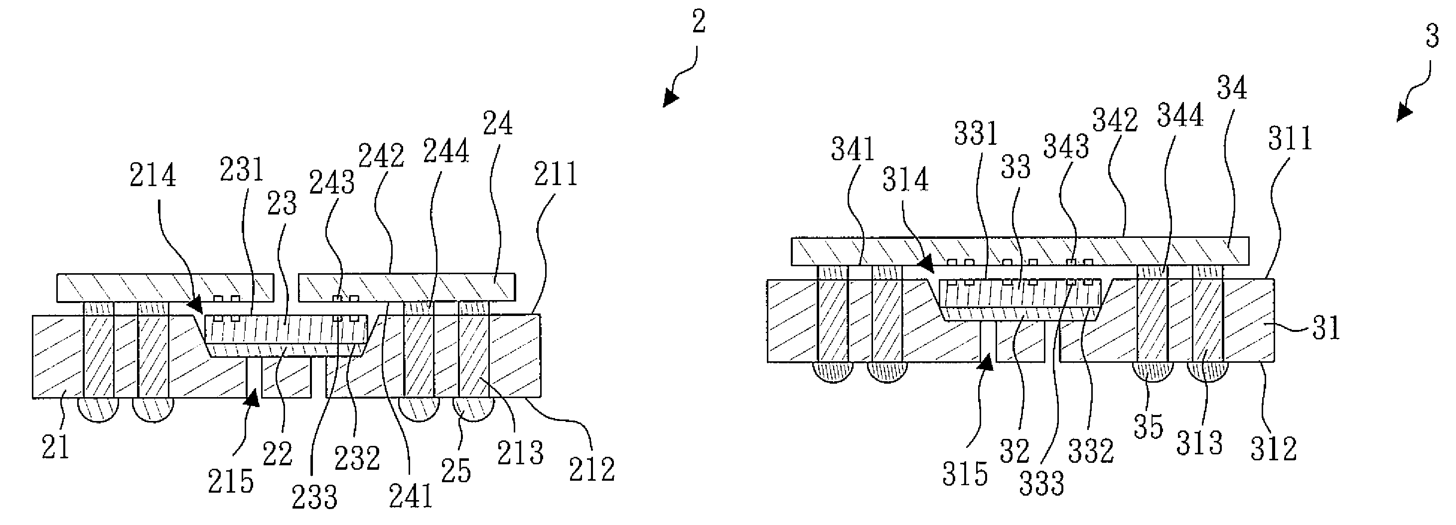
[0022]FIGS. 8 to 15 show a method for making a semiconductor package according to the present invention. Referring to FIGS. 8 and 9, a silicon substrate 20 is provided. The silicon substrate 20 comprises a plurality of silicon substrate units 21. Each silicon substrate unit 21 has a top surface 211, a bottom surface 212, a cavity 214 and a plurality of vias 213. The cavity 214 opens at the top surface 211, and the vias 213 penetrate the silicon substrate unit 21 and are disposed around the cavity 214. Preferably, each silicon substrate unit 21 further has at least one through hole 215 for venting air. One end of the through hole 215 opens at the bottom of the cavity 214, and the other end of the through hole 215 opens at the bottom surface 212 of the silicon substrate unit 21. Referring to FIG. 10, a plurality of glue layers 22 are formed in the cavities 214.
[0023]Referring to FIG. 11, a plurality of bridge chips 23 are provided. Each bridge chip 23 has an active surface 231, a back...
second embodiment
[0036]FIGS. 16 to 23 show another method for making a semiconductor package according to the present invention. Referring to FIGS. 16 and 17, a silicon substrate 30 is provided. The silicon substrate 30 comprises a plurality of silicon substrate units 31. Each silicon substrate unit 31 has a top surface 311, a bottom surface 312, a cavity 314 and a plurality of vias 313. The cavity 314 opens at the top surface 311, and the vias 313 penetrate the silicon substrate unit 31 and are disposed around the cavity 314. Preferably, each silicon substrate unit 31 further has at least one through hole 315 for venting air. One end of the through hole 315 opens at the bottom of the cavity 314, and the other end of the through hole 315 opens at the bottom surface 312 of the silicon substrate unit 31. Referring to FIG. 18, a plurality of glue layers 32 are formed in the cavities 314.
[0037]Referring to FIG. 19, a plurality of bridge chips 33 are provided. Each bridge chip 33 has an active surface 33...
third embodiment
[0047]FIGS. 24 to 37 show a method for making a semiconductor package according to the present invention. Referring to FIG. 24, a carrier 41 is provided. In the embodiment, the carrier 41 is a wafer having a release film 42 thereon. Referring to FIG. 25, a plurality of active chips 43, 44 are provided. The active chip 43 has a has an active surface 431, a back surface 432, a plurality of non-contact pads 433 and a plurality of conducting pads 434. The non-contact pads 433 and conducting pads 434 are disposed adjacent to the active surface 431. The active chip 44 has a has an active surface 441, a back surface 442, a plurality of non-contact pads 443 and a plurality of conducting pads 444. The non-contact pads 443 and conducting pads 444 are disposed adjacent to the active surface 441. Then, the active surfaces 431, 441 of the active chips 43, 44 are attached to the carrier 41. In the embodiment, the active surfaces 431, 441 of the active chips 43, 44 are attached to the release film...
PUM
 Abstract
Description
Claims
Application Information
 - R&D
- Intellectual Property
- Life Sciences
- Materials
- Tech Scout
- Unparalleled Data Quality
- Higher Quality Content
- 60% Fewer Hallucinations
Browse by: Latest US Patents, China's latest patents, Technical Efficacy Thesaurus, Application Domain, Technology Topic, Popular Technical Reports.
© 2025 PatSnap. All rights reserved.Legal|Privacy policy|Modern Slavery Act Transparency Statement|Sitemap|About US| Contact US: help@patsnap.com


