DC brushless motor drive circuit with speed variable-voltage

a brushless motor and variable voltage technology, applied in the direction of motor/generator/converter stopper, dynamo-electric gear control, dynamo-electric converter control, etc., can solve the problem of insufficient drive torque, and achieve the effect of improving rotational speed and overriding the increase in the inductive impedance of the magnetic field winding

Active Publication Date: 2012-10-16
YANG TAI HER
View PDF1 Cites 559 Cited by
  • Summary
  • Abstract
  • Description
  • Claims
  • Application Information

AI Technical Summary

Benefits of technology

[0006]The DC brushless motor drive circuit with speed variable-voltage of the present invention relates to a drive circuit of the DC brushless motor driven by DC power supply and equipped with the electric machinery angle position detection device, in which the DC brushless motor is under various rotational speeds statuses produced on the basis of the magnitude of the input voltage and the load, through the output speed detection device detecting the variation of the rotational speed, and the voltage input into the DC brushless motor is relatively increased or decreased according to the internal setting of the motor drive control device, to form a closed loop drive circuit; especially, during the operation at the range of high rotational speed, through the detected increased rotational speed detected by the output speed detection device to further increase the input voltage of the DC brushless motor according to the setting of the motor drive control device, thereby to overcome the increased inductive impedance of the magnetic field winding resulting from the increased rotational speed of the DC brushless motor by inputting larger current for providing the current of the DC brushless motor to produce required torque.

Problems solved by technology

Therefore, the following shortcoming exists, when the DC voltage input to the DC brushless motor is higher, and the speed of the electric machinery is accordingly faster, if the driven load is increased, because the inductive reactance of the electric machinery is too high, the original input voltage is not enough to increase the input excitation current with the increased load, thus the drive torque is not enough.

Method used


Image

  • DC brushless motor drive circuit with speed variable-voltage
  • DC brushless motor drive circuit with speed variable-voltage

Examples


Embodiment Construction

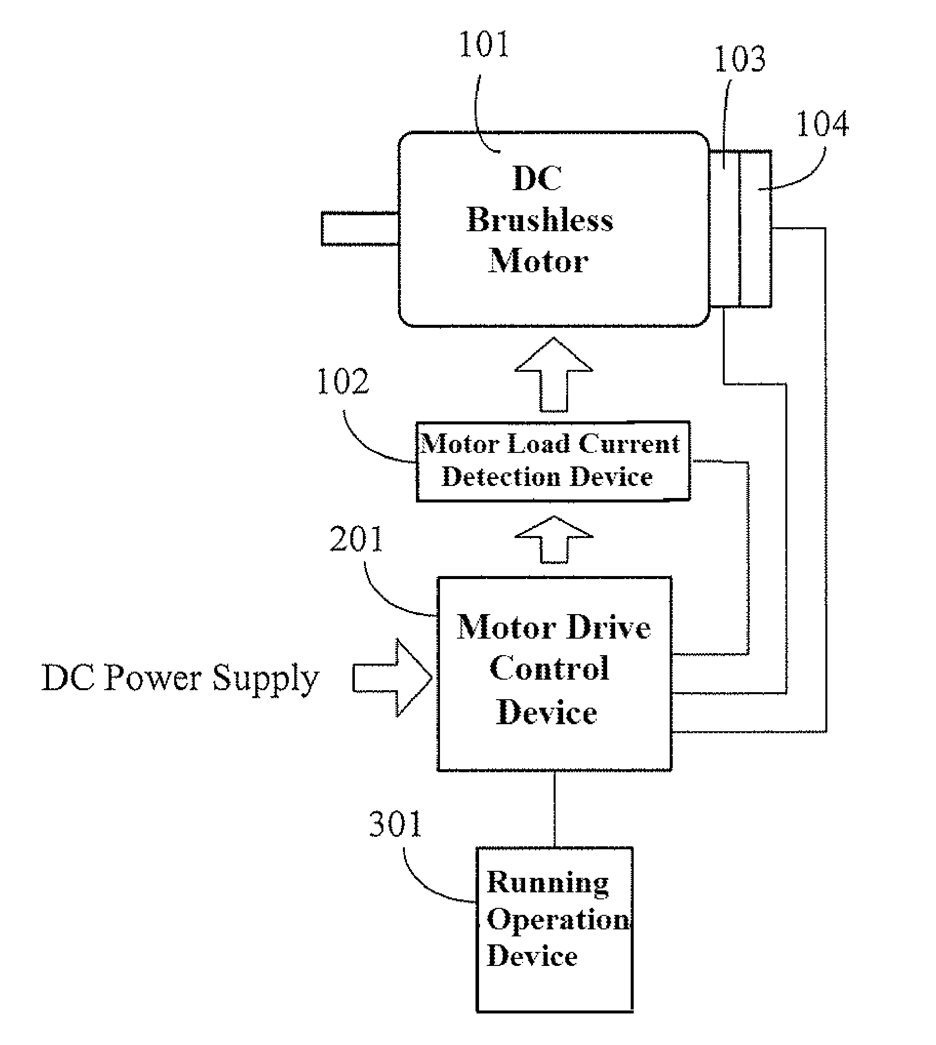
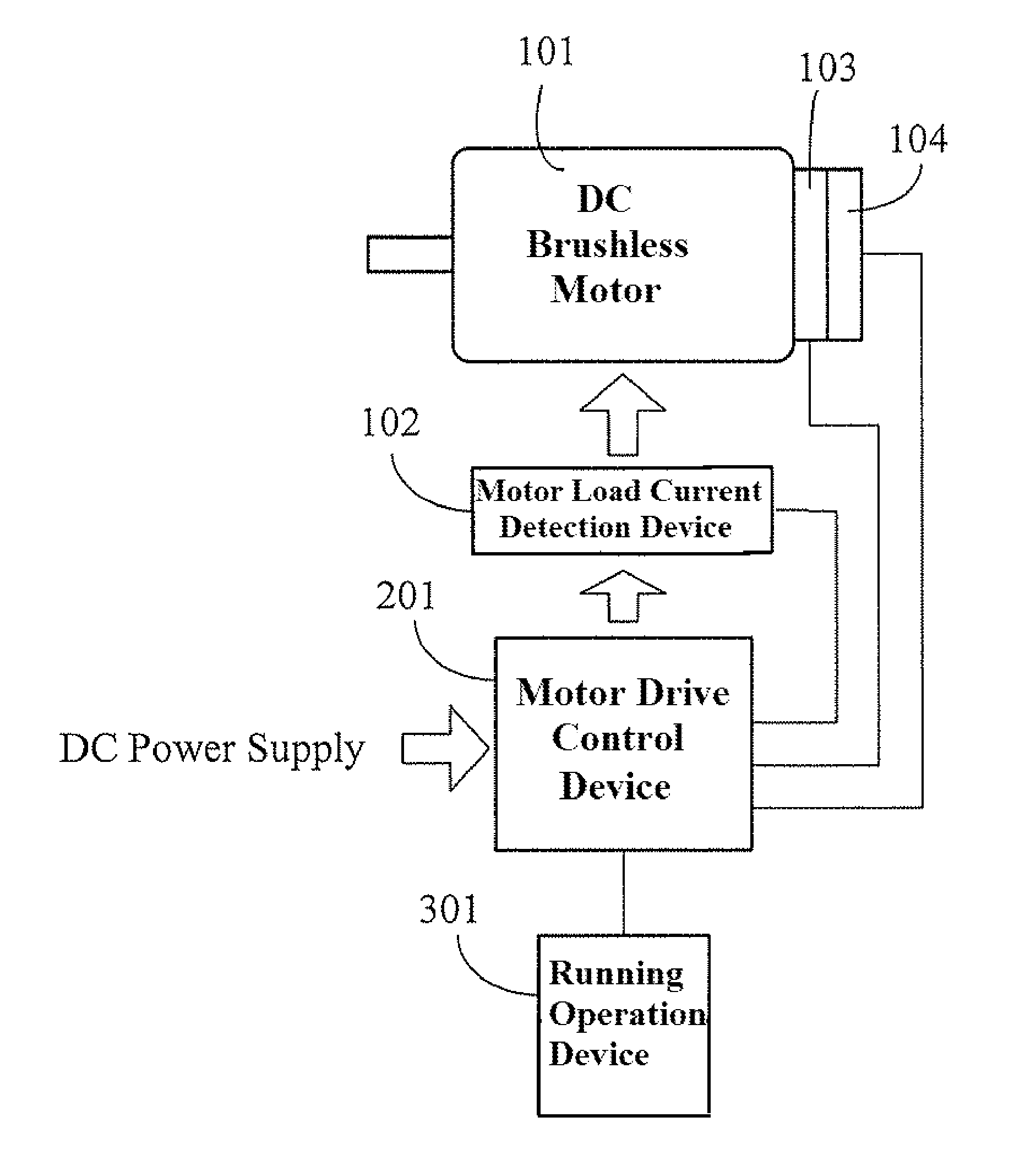
[0014]The DC brushless motor drive circuit with speed variable-voltage of the present invention relates to a drive circuit of the DC brushless motor driven by DC electric power and equipped with the electric machinery angle position detection device, in which the DC brushless motor is under various running speeds statuses produced on the basis of the magnitude of the input voltage and the load, through the output speed detection device detecting the variation of the rotational speed, and the voltage input into the DC brushless motor is relatively increased or decreased according to the internal setting of the motor drive control device, to form a closed loop drive circuit; especially, during the operation at the range of high rotational speed, through the detected increased rotational speed detected by the output speed detection device to further increase the input voltage of the DC brushless motor according to the setting of the motor drive control device, thereby to overcome the i...


PUM


Abstract

For the present invention, under various running speeds statuses, the voltage supplied to the DC brushless motor is relatively increased or decreased on the basis of the internal setting of the motor drive control device according to the increased or decreased rotational output speed, so as to prevent the shortcoming of too much variation of the input impedance caused by the inductive reactance of the winding accordingly changed when the speed of the DC brushless motor is changed, specifically, to prevent the shortcoming of unable producing required torque resulting from the increased inductive reactance caused by increasing the rotational speed which makes the current value become too low when input by the original working voltage.

Description

BACKGROUND OF THE INVENTION[0001](a) Field of the Invention[0002]For the DC brushless motor drive circuit with speed variable-voltage of the present invention, a closed loop drive circuit is formed, in which, under various running speeds statuses, the voltage supplied to the DC brushless motor is relatively increased or decreased on the basis of the internal setting of the motor drive control device according to the increased or decreased output rotational speed, so as to prevent the shortcoming of too much variation of the input impedance caused by the inductive reactance of the winding accordingly changed when the speed of the DC brushless motor is changed, specifically, to prevent the shortcoming of unable producing required torque resulting from the increased inductive reactance caused by increasing the rotational speed which makes the current value become too low when input by the original working voltage.[0003](b) Description of the Prior Art[0004]The DC brushless motor is usu...

Claims


Application Information

Patent Timeline
Patent Type & Authority Patents(United States)
IPC IPC(8): H02P23/00
CPCH02P6/08H02P6/10
Inventor YANG, TAI-HER
Owner YANG TAI HER
Why Eureka
Try Eureka