Head assembly, magnetic disk drive apparatus and rotation mechanism

a technology of magnetic disk drive and rotating mechanism, which is applied in the direction of integrated arm assemblies, instruments, and record information storage, etc., can solve the problems of unstable slider attitude angle, difficult to ensure stability in fine adjustment inability to precisely position the magnetic head so as to achieve adjustment and stability of slider attitude angle, the effect of high recording density

Active Publication Date: 2012-10-16
TDK CORPARATION +1
View PDF9 Cites 4 Cited by
  • Summary
  • Abstract
  • Description
  • Claims
  • Application Information

AI Technical Summary

Benefits of technology

[0016]The present invention has been developed for solving the above-described problems of the related art. It is therefore an object of the present invention to provide a head assembly, which, without affecting the displacement characteristics of a head, achieves adjustment and stability of the attitude angle of a slider, and can write and read data with high recording density, to provide a magnetic disk drive apparatus with the head assembly, and to provide a rotation mechanism.
[0018]Both of the extended lines of the first and second link parts travel toward the fulcrum position supporting the slider to freely turn and intersect with each other. Therefore, it is possible to have sufficient rigidity in the rolling direction and the pitching direction and to secure an amount of displacement of the head without giving turning load for the turning movement of the slider in the yawing direction. Also, because a preload or internal force of pushing the slider against the fulcrum protrusion is ensured, stabilized control of the attitude angle of the slider can be achieved avoiding occurrence of damage in disk under the loading / unloading operation. That is, when micro-displacement control of the head is required for tracking correction on the magnetic disk, it is possible to maintain the response characteristics of the head at high speed with high precision. Furthermore, it is possible to provide a head assembly and a magnetic disk drive apparatus in which the number of components is reduced to have reduced weight and reduced size. Moreover, since the slider and the slider support plate turn around the fulcrum protrusion, pressure and load on the drive element during operation are greatly reduced, causing deterioration or damage of the drive element to prevent from occurrence. As a result, it is possible to greatly improve durability of the head assembly.
[0021]It is further preferred that each of the first linear link part and the second linear link part is formed by bending a part of a plate member integrally formed with the slider support plate. This enables a link mechanism to be formed with a simple structure.
[0022]It is still further preferred that a bending direction of the part of the plate member integrally formed with the slider support plate is a direction to a surface of the plate member opposite to a surface on which the at least one drive element is mounted. Bending to this direction can prevent the occurrence of inconvenience, such as vibration caused by resonance at a specific frequency.
[0023]It is further preferred that the first top end joint part, the first base end joint part, the second top end joint part and the second base end joint part comprise portions with locally weakened rigidity. This makes the mechanical load of the slider in the yawing direction smaller as much as possible to smoothly perform fine positioning of the head.

Problems solved by technology

However, in case that the head-actuator arm is merely turned by the VCM to position the magnetic head, the positioning of the magnetic head cannot be made precise so much.
However, according to the micro-displacement mechanism disclosed in Japanese patent publication 2002-324374A, the following problems may arise when performing loading operation in which the slider 224 moves above the magnetic disk and unloading operation in which the slider 224 saves from the magnetic disk.
Therefore, it has been difficult to ensure stability in fine adjustment of the attitude angle of the slider, and to regulate this attitude angle.
Moreover, because the preload or internal force of pushing the slider support plate with the mounted slider against the fulcrum protrusion is small, the slider support plate is easily separated from the fulcrum protrusion, resulting in possibility that the attitude angle of the slider may become unstable at the time of loading operation and unloading operation and that the magnetic disk may be damaged.
Whereas according to the micro-displacement mechanism disclosed in Japanese patent publication 2001-052456A, since the slider is supported only by a pair of plate-shaped arm parts made of an elastic material, the bending rigidity of the elastic material becomes larger than that of the piezoelectric element and therefore it is impossible to obtain sufficient displacement.
Also, it is difficult to stably keep the attitude angle of the slider at the time of loading operation and unloading operation.

Method used


Image

  • Head assembly, magnetic disk drive apparatus and rotation mechanism
  • Head assembly, magnetic disk drive apparatus and rotation mechanism
  • Head assembly, magnetic disk drive apparatus and rotation mechanism

Examples


Embodiment Construction

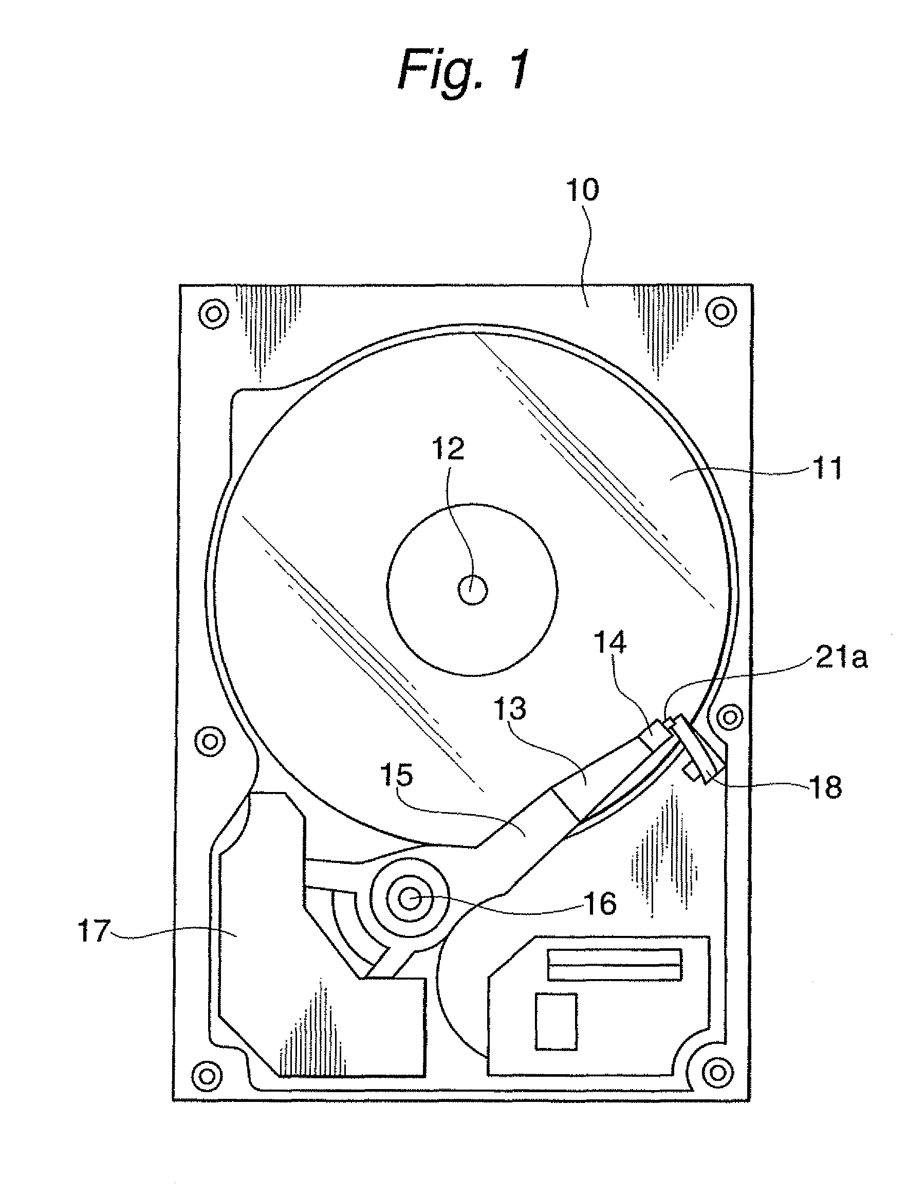
[0064]FIG. 1 schematically illustrates the overall structure of a load / unload type HDD apparatus as an embodiment of a magnetic disk drive apparatus according to the present invention.

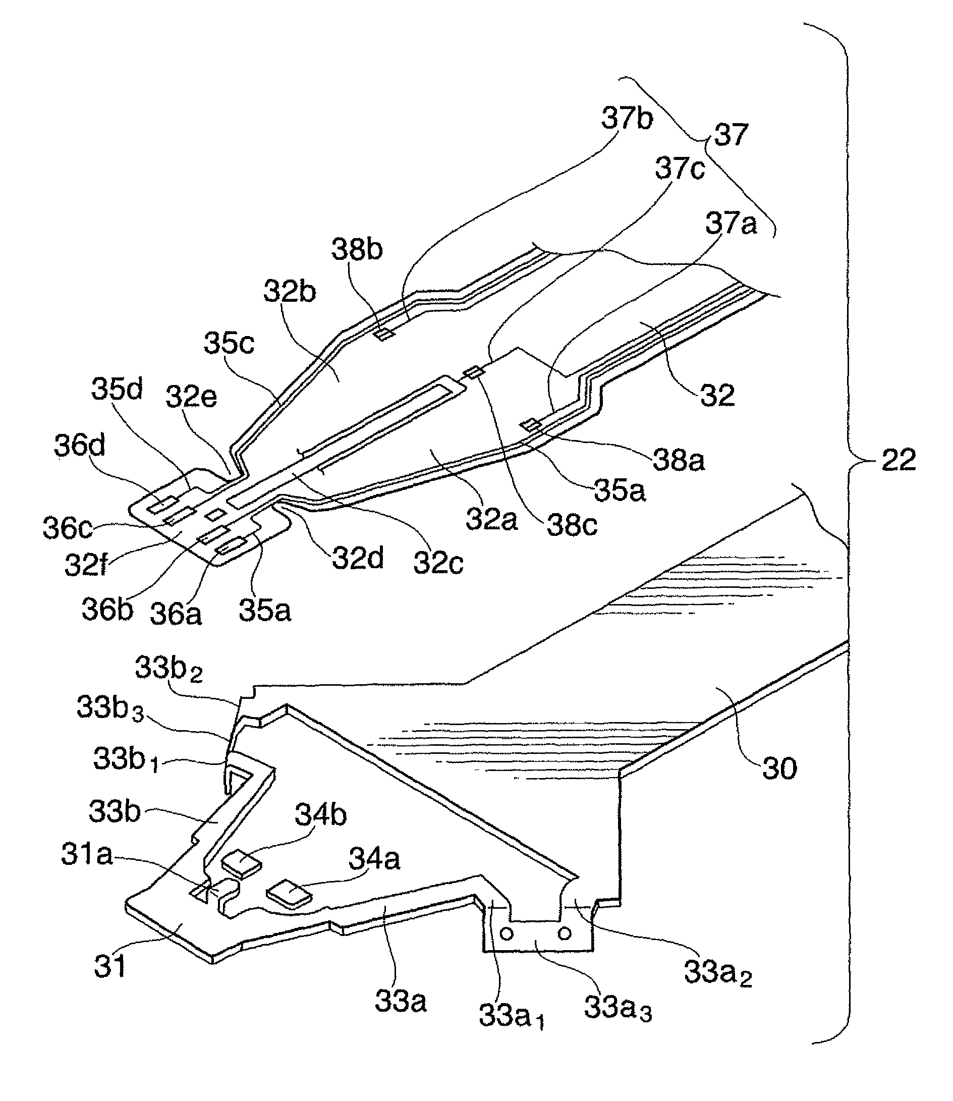
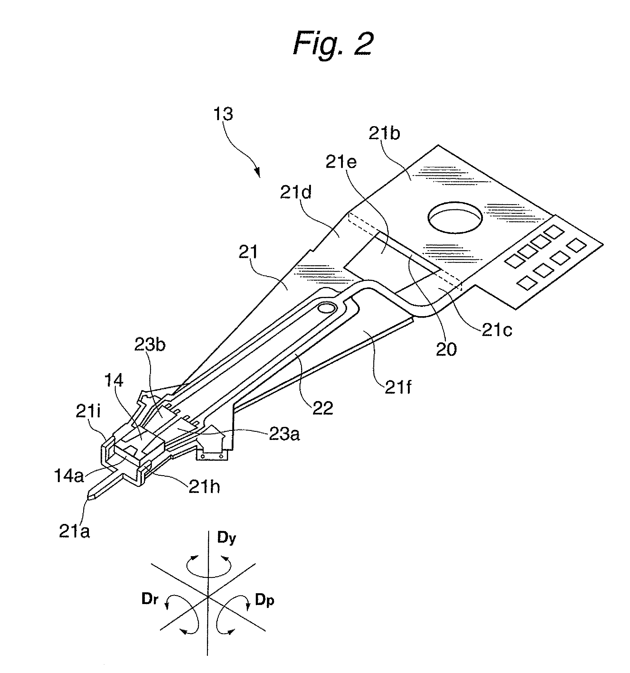
[0065]In the figure, reference numeral 10 denotes a housing of the HDD apparatus, 11 a magnetic disk driven by a spindle motor to rotate around a shaft 12, 13 a head assembly on which a slider 14 with a magnetic head element is mounted at its top end section, and 15 a support arm for supporting this head assembly 13 at its top end section, respectively.

[0066]At a rear end section of the support arm 15, mounted is a coil part of a voice coil motor (VCM). The arm 15 is capable of turning around a horizontal turning axis 16 in a plane parallel to a surface of the magnetic disk 11. The VCM is composed of the coil part and a magnet part 17 covering the coil part. The HDD apparatus has a ramp mechanism 18 disposed above a region from the outside of a data area of the disk 11 to the outside of the disk 11. A ...


PUM

PropertyMeasurementUnit
lengthaaaaaaaaaa
lengthaaaaaaaaaa
attitude angleaaaaaaaaaa

Abstract

A head assembly includes a slider having a head element, a load beam, a fulcrum formed at a top end section of the load beam, a slider support plate for supporting the slider to freely turn around the fulcrum, at least one drive element for applying a turning force to the slider support plate in a plane thereof, a first linear link part having at both ends a first top end joint part mechanically connected to the slider support plate, and a first base end joint part mechanically connected to the load beam, and a second linear link part having at both ends a second top end joint part mechanically connected to the slider support plate, and a second base end joint part mechanically connected to the load beam. Both of an extended line of the first linear link part and an extended line of the second linear link part travel toward a position of the fulcrum and intersect with each other.

Description

BACKGROUND OF THE INVENTION[0001]1. Field of the Invention[0002]The present invention relates to a head assembly suitable for attaining higher recording density of a magnetic disk drive apparatus used in such as a storage apparatus of a computer, to a magnetic disk drive apparatus with the head assembly, and to a rotation or turning mechanism.[0003]2. Description of the Related Art[0004]Recently, the recording density of a magnetic disk used in a magnetic disk drive apparatus becomes increasingly higher. Such magnetic disk drive apparatus has generally a slider on which a magnetic head for recording and / or reproducing data in / from the magnetic disk is mounted. The slider is supported by a head support mechanism. The head support mechanism has a head-actuator arm to which the slider is attached. This head-actuator arm is able to turn by a voice coil motor (VCM). Positioning of the magnetic head mounted on the slider to an arbitrary position on the magnetic disk is performed by contro...

Claims


Application Information

Patent Timeline
Patent Type & Authority Patents(United States)
IPC IPC(8): G11B21/21
CPCG11B5/4873G11B5/4833G11B5/484G11B5/483
Inventor KUWAJIMA, HIDEKI
Owner TDK CORPARATION
Why Eureka
Try Eureka