Bipod for light-weight machine gun

a machine gun and lightweight technology, applied in the field of firearms, can solve the problems of difficult to maintain accurate targeting, heavy guns, complicated devices of current bipods, etc., and achieve the effects of improving stability, improving safety of yoke attachment, and improving strength and detention

Active Publication Date: 2012-10-23
FN AMERICA
View PDF49 Cites 24 Cited by
  • Summary
  • Abstract
  • Description
  • Claims
  • Application Information

AI Technical Summary

Benefits of technology

[0011]An important feature of the present invention is the improved security of the attachment of the yoke to the body. The use of a stepped screw with compression spring assures a firm hold between the two.
[0012]Another important feature is the larger feet of the telescoping legs. The larger feet are more than an inch and one half in diameter as opposed to less than an inch for better stability on softer ground.
[0013]Still another feature of the present invention is the use of pivot pins each comprising a pin assembly formed by placing a cylinder within a cylinder to allow the two legs to pivot with respect to the body. The pin assembly consists of an inner coiled cylinder captured by an outer slotted cylinder. The inner cylinder exerts and distributes spring pressure uniformly absorbing shock and vibration outwards against the slotted cylinder to increase strength and detention.

Problems solved by technology

Machine guns are heavy, they become quite hot when fired, and the forces associated with rapid firing makes it difficult to maintain accurate targeting unless the muzzle end is properly supported.
Far from just a simple inverted V, current bipods are more complicated devices that include telescoping legs, swivel mounts, and folding structures.
One significant drawback to the prior art is that the bipod legs must be deployed separately, i.e. the legs must be unfolded one at a time rather than with a single motion.
The releasing mechanisms that allow the legs to telescope and fold, such as the one disclosed by Curtis, are often overly complex, unreliable, or create a device that is somewhat unwieldy when transported in a small vehicle.
Many of the designs, such as the one employing tubular legs with frictional locks as disclosed by Keng, are not suitable for military applications because they are not suitable for combat; dirt or damage to the legs can interfere with the telescoping.
The bipod disclosed in related patent, U.S. Pat. No. 6,763,627, issued to Kaempe, while a significant improvement over the prior art, also suffers in the rugged environment of use.
Certain parts loosen or break, such as the e-clip, or become clogged with dirt or sand making the deployment of the legs of the bipod difficult.

Method used


Image

  • Bipod for light-weight machine gun
  • Bipod for light-weight machine gun
  • Bipod for light-weight machine gun

Examples


Embodiment Construction

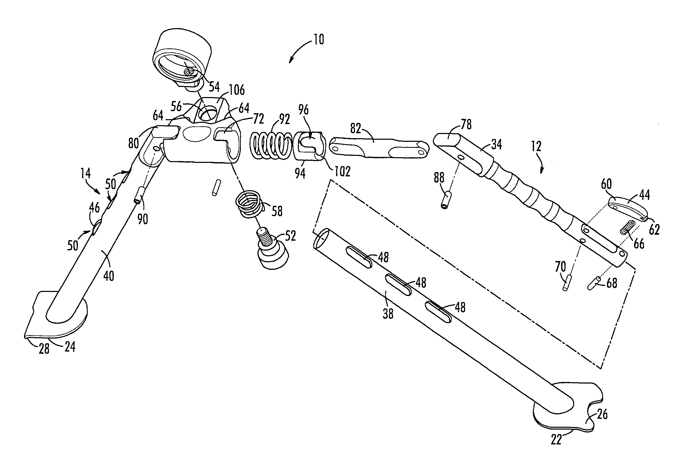
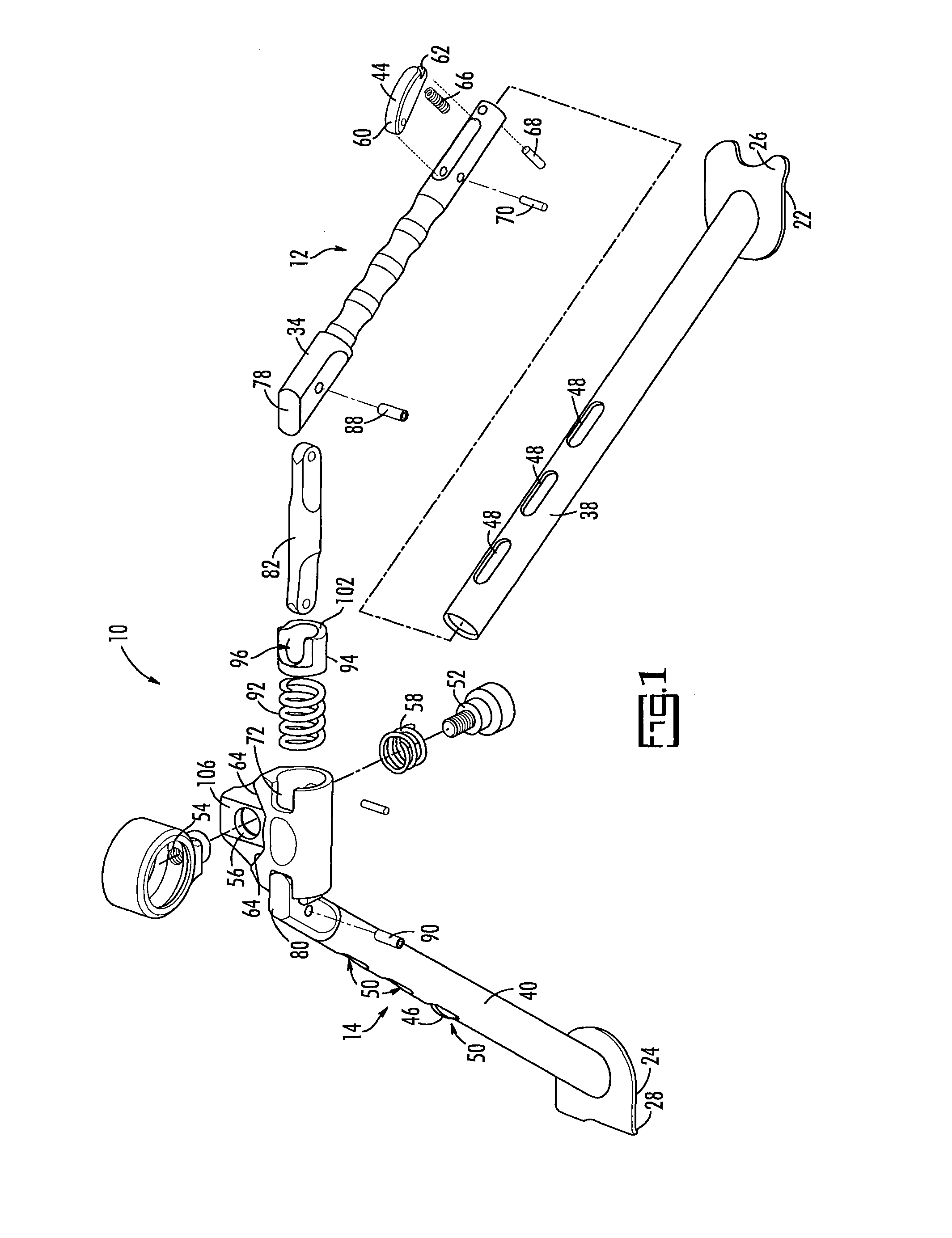
[0026]The preferred embodiment of the present invention is a bipod with telescoping legs that can be deployed with one hand.

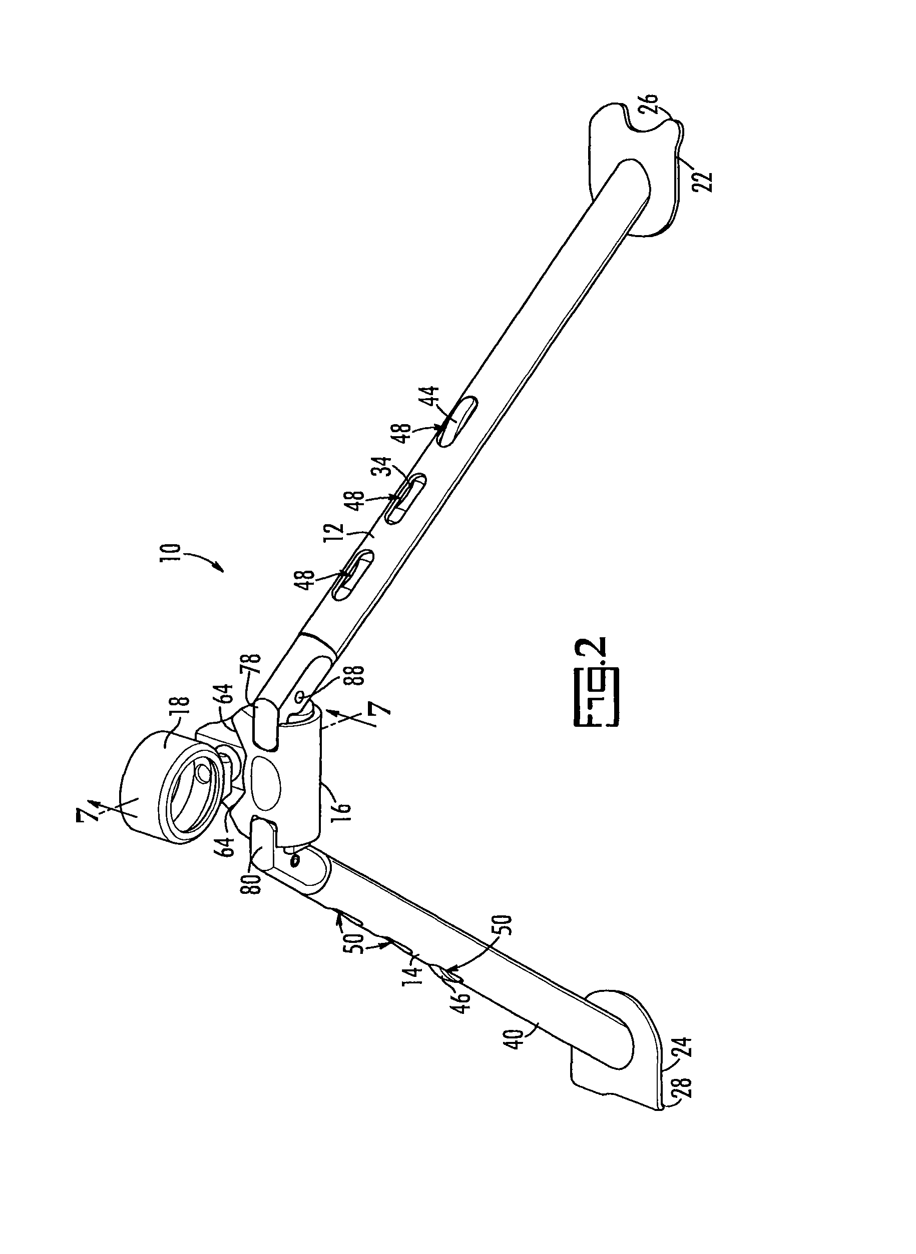
[0027]Referring now to FIGS. 1 and 2, there are shown perspective exploded and assembled views of a preferred embodiment of the present invention, namely, a bipod for a light-weight machine gun generally indicated by reference number 10. Bipod 10 has two legs 12 and 14 that are attached to a body 16. Body 16 supports a yoke 18 that is dimensioned for encircling the barrel of a firearm such as a machine gun.

[0028]Bipod 10 is shown in the deployed configuration in FIGS. 1 and 2, with legs 12 and 14 splayed to provide stability. Each leg 12, 14, has a foot 22, 24, respectively, that engages the ground or other surface and is preferably formed to resist lateral movement. For secure footing, feet 22, 24, are large and have teeth 26, 28, respectively, to bite into a surface such as the ground or a sandbag, for example, and resist lateral movement. Feet are large to b...


PUM


Abstract

A bipod for a light-weight machine gun is disclosed. The bipod has tubular telescoping legs with large ground-engaging feet that may be extended and retracted to discreet locking positions. The bipod has a spring-based system that allows a user to pivot the bipod legs about cylinder-in-a-cylinder pivot pins, either towards or away from the barrel muzzle with one hand, thus giving 180 degrees of travel. The bipod is attachable to a machine gun with a round yoke using a stepped screw and compression spring that assures yoke remains tightly secured to body, but rotatable for traversing, during extended use.

Description

CROSS-REFERENCE TO RELATED APPLICATIONS[0001]The priority benefit of U.S. provisional patent application 61 / 107,555, filed Oct. 22, 2008, which is incorporated herein in its entirety by reference, is claimed. This application is related to U.S. Pat. No. 6,763,627 issued to the present applicant Jul. 20, 2004, and which is incorporated herein in its entirety by reference.BACKGROUND OF THE INVENTION[0002]The present invention relates to firearms, and specifically to bipods for use with a light-weight machine gun. A machine gun is not a shoulder-fired weapon like a rifle. It may be fired from the hip but is best fired when supported at the muzzle end by a bipod or other structure. Machine guns are heavy, they become quite hot when fired, and the forces associated with rapid firing makes it difficult to maintain accurate targeting unless the muzzle end is properly supported.[0003]A bipod has been a staple accessory for many military firearms since the beginning of firearm development. T...

Claims


Application Information

Patent Timeline
Patent Type & Authority Patents(United States)
IPC IPC(8): F41C27/00
CPCF41A23/10
Inventor HASS, KEVIN M.SEWELL, ROBERT WAYNESCHMITTER, EDWARD P.
Owner FN AMERICA
Why Eureka
Try Eureka