Modular entrance floor system

a floor system and module technology, applied in the direction of flooring, treads, cleaning equipments, etc., can solve the problems of prone to the same installation and maintenance problems as roll-up designs, the capacity of such a floor mat to accumulate foreign materials is generally limited, and the handling of cumbersome gratings can prove hazardous

Active Publication Date: 2012-10-23
E M E H
View PDF68 Cites 65 Cited by
  • Summary
  • Abstract
  • Description
  • Claims
  • Application Information

AI Technical Summary

Problems solved by technology

The size and weight of such large gratings presents numerous problems with respect to installation and maintenance as handling of such cumbersome gratings can prove hazardous and require assistance by numerous service personnel.
Consequently, these roll-up designs are prone to the same installation and maintenance problems referred to above.
The capacity of such a floor mat to accumulate foreign material is generally limited by the amounts which may be retained in the tread material.
As these spaces fill with dirt or become saturated with water, the floor mat tends to lose its ability to clean the footwear of pedestrians passing across the mat.
Also, the tread surfaces of such floor mats are generally not replaceable and lack the strength and durability of rigid rails.
However, pedestrian traffic tends to be concentrated to a narrow strip, e.g., the strip of entrance flooring aligned with a doorway, thereby resulting in uneven usage and accumulation of debris across the entrance floor area.
The prior art designs do not allow a custodian to access and / or replace only a portion of the entrance floor area.
Such a configuration leads to greater complexity and higher maintenance time and associated costs.
Additionally, the prior art entrance floor designs may not provide sufficient free or “fall-through” area in the top surface for which debris may pass through.
Thus, the top surface of the entrance floor may retain water and / or debris resulting in a slick surface which poses a safety hazard to pedestrians.

Method used


Image

  • Modular entrance floor system
  • Modular entrance floor system
  • Modular entrance floor system

Examples


Embodiment Construction

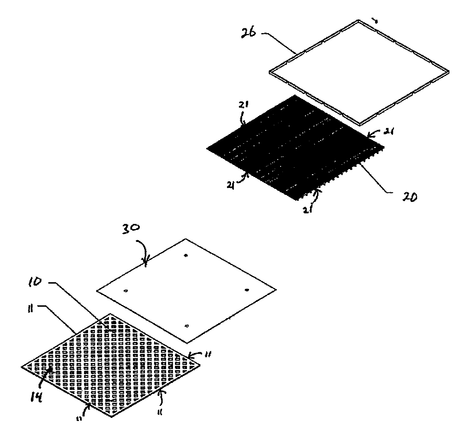
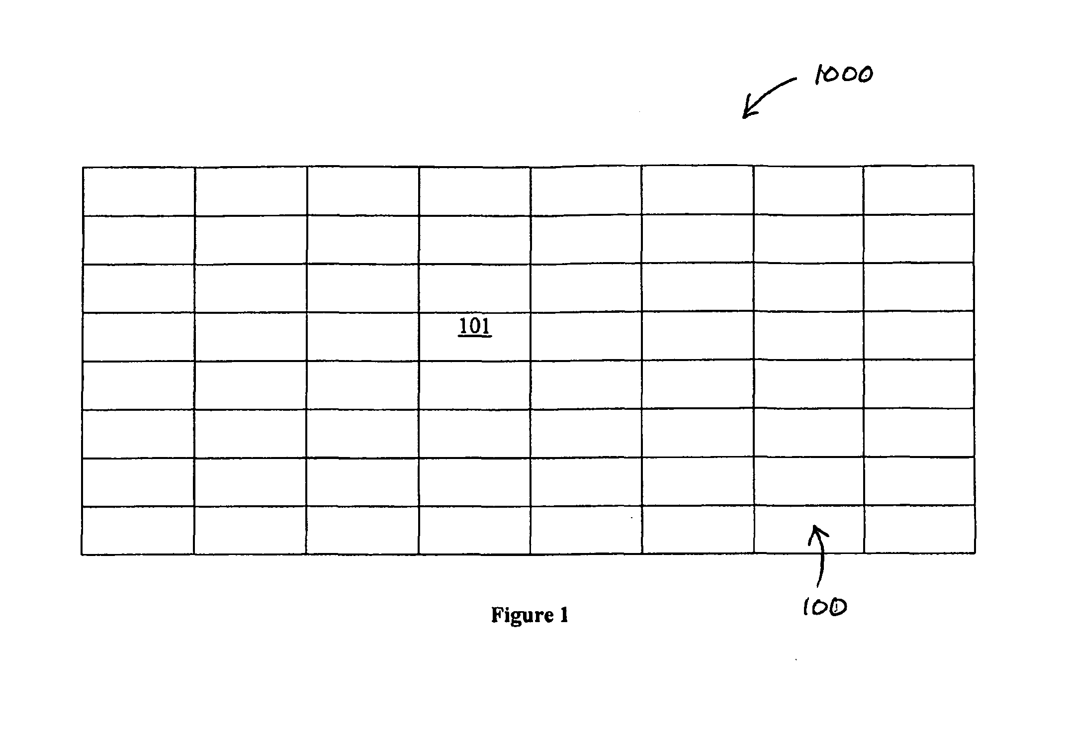
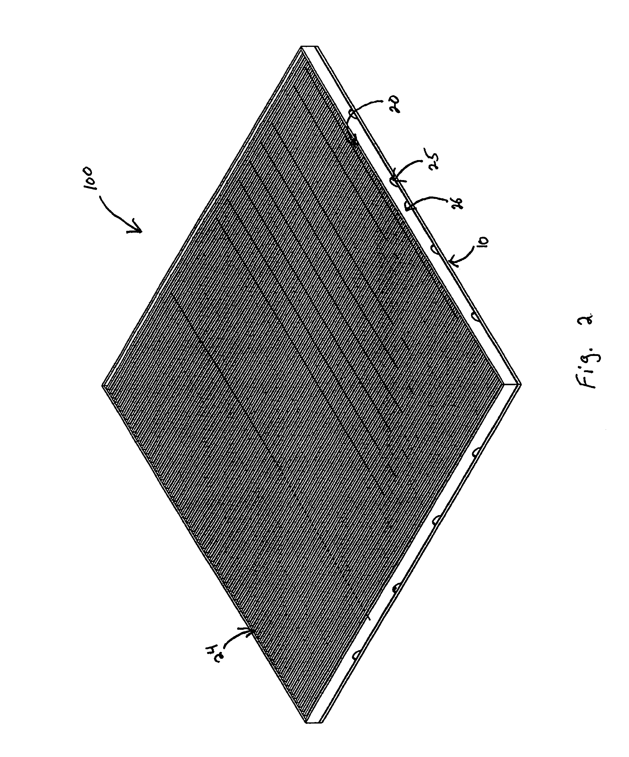
[0028]Reference will now be made in detail to the exemplary embodiments of the disclosed subject matter, examples of which are illustrated in the accompanying drawings. The methods and corresponding steps of the disclosed subject matter will be described in conjunction with the detailed description of the system. The methods and systems presented herein may be used for an entrance floor area. The disclosed subject matter is particularly suited for a modular entrance floor area having a variety of designs and aesthetic features.

[0029]In accordance with an aspect of the disclosed subject matter, a plurality of floor sections are positioned adjacent to each other to define an entrance floor area. Each individual floor section includes a base and a surface plate. The surface plate is removably attached to the base plate and can include at least one drain feature. The plurality of floor sections are configured such that the surface plate of one floor section is interchangeable with anoth...


PUM


Abstract

A modular entrance floor system comprising a plurality of floor sections, the plurality of floor sections being disposed adjacent each other and defining a perimeter of an entrance floor area. Each floor section includes a base plate permanently coupled to a foundation, and a surface plate removably attached to the base plate. The surface plate has at least one drain feature. The plurality of floor sections are configured such that the surface plate of a first floor section is interchangeable with the surface plate of a second floor section, independent of the adjacent floor sections.

Description

BACKGROUND OF THE DISCLOSED SUBJECT MATTER[0001]1. Field of the Disclosed Subject Matter[0002]The disclosed subject matter relates to an entrance floor system for use in residential or commercial establishments. Particularly, the present disclosed subject matter is directed to a modular entrance floor system comprising a plurality of floor sections and a method for interchanging select floor sections.[0003]2. Description of Related Art[0004]A variety of flooring designs and construction methods are known for entrance ways to office buildings, stores, residences and the like which are frequently provided with gratings which are recessed into the foundation so as to be flush with the floor surface. These gratings are designed to facilitate the removal of debris, such as dirt, snow, water and the like from the footwear of pedestrian traffic entering the structure.[0005]Typical forms of such entrance gratings comprise a plurality of elongated rigid rails arranged in side-by-side, parall...

Claims


Application Information

Patent Timeline
Patent Type & Authority Patents(United States)
IPC IPC(8): E04C2/42E04C2/34
CPCE04C2/42E04F15/02A47L23/22E04F15/02183E04F15/02194
Inventor GARD, JOHN LEAVITTADAMS, DAVID E.PERKINS, NANCY JANE
Owner E M E H
Why Eureka
Try Eureka