Cutting device and manufacturing method for absorptive article

a cutting device and absorptive technology, applied in the field of cutting devices and manufacturing methods for absorptive articles, can solve the problems of poor appearance, manufacturing defects, bond failure, etc., and achieve the effect of suppressing manufacturing defects and poor appearan

Inactive Publication Date: 2012-10-23
UNI CHARM CORP
View PDF4 Cites 6 Cited by
  • Summary
  • Abstract
  • Description
  • Claims
  • Application Information

AI Technical Summary

Benefits of technology

[0013]The present invention can provide the cutting device and the manufacturing method for the absorptive article, which can suppress the manufacturing defects or a poor appearance caused in the absorptive article.

Problems solved by technology

Incidentally, it is important that the end-product absorptive article have a cut surface substantially parallel to a direction (hereinafter, a CD direction) crossing the MD direction, since the cut surface inclined relative to the CD direction can possibly cause manufacturing defects (e.g., bond failure), a poor appearance, or the like in the absorptive article.
In the above-mentioned conventional cutting device, however, the continuous portion of the web traveling from the continuous portion transport unit to the press-contact region is unheld / unnipped by the continuous portion transport unit.
This can possibly lead to a displacement of the cut surface of the web when the cutting blade cuts the web.
This causes the problem that the cut surface may be inclined relative to the CD direction, thereby causing the manufacturing defects or poor appearance in the absorptive article obtained through the cutting.

Method used


Image

  • Cutting device and manufacturing method for absorptive article
  • Cutting device and manufacturing method for absorptive article
  • Cutting device and manufacturing method for absorptive article

Examples


Embodiment Construction

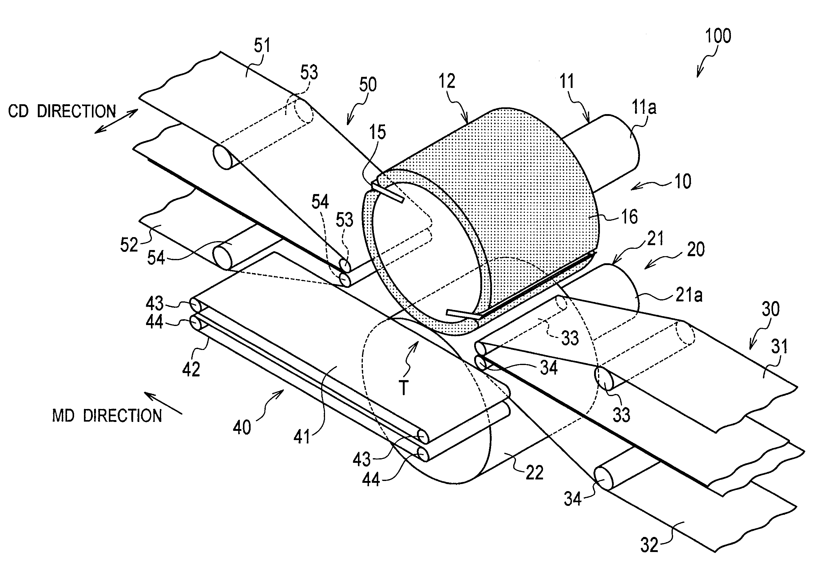
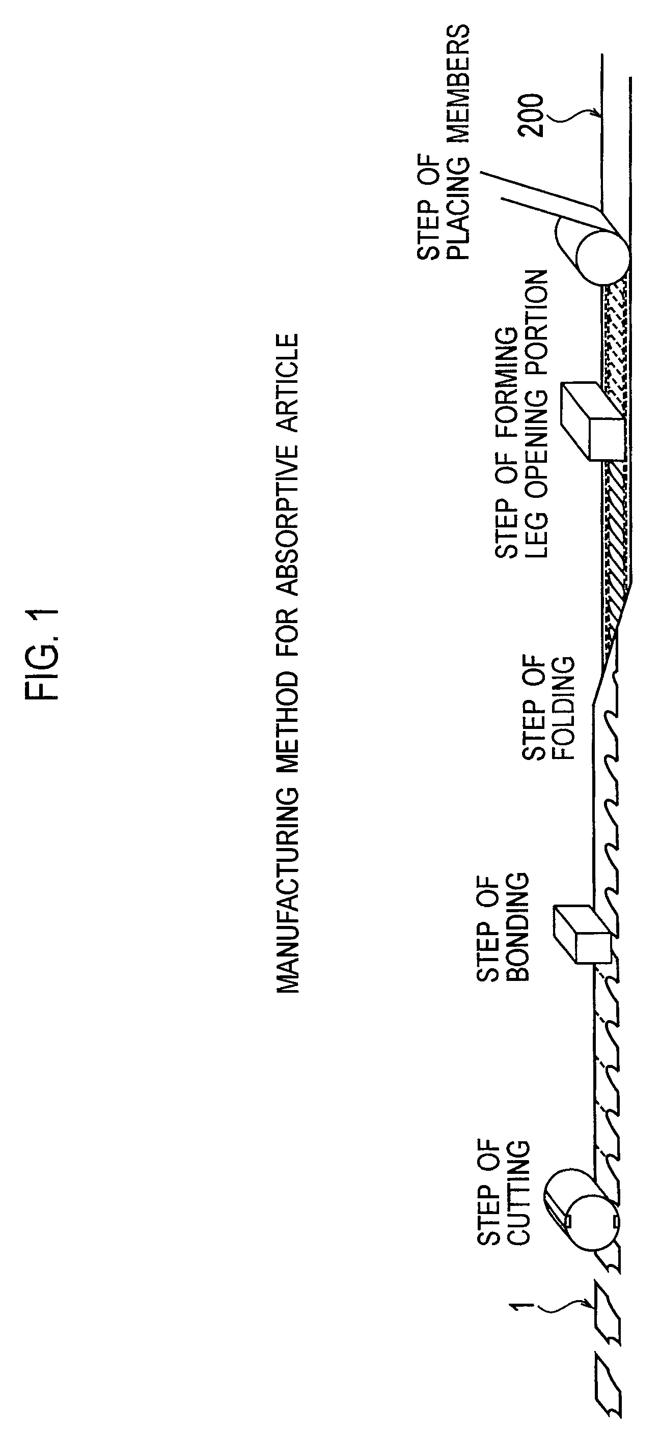
[0022]Description will be given below with reference to the drawings with regard to embodiments of the present invention. Specifically, description will be given with regard to (1) a manufacturing method for an absorptive article, (2) the configuration of a cutting device, (3) the configuration of a continuous portion transport unit, (4) the configuration of a discontinuous portion transport unit, (5) the configuration of an article transport unit, (6) operations and effects, (7) modified embodiments, and (8) other embodiments.

[0023]Note that, throughout the drawings, the same or similar parts are designated by the same or similar reference numerals. It should be noted that the drawings are in schematic form and dimensional ratios and others therein are different from actual ones.

[0024]It is to be therefore understood that specific dimensions and others should be determined based on the following description. Of course, it will be also understood that differences may be existed in t...


PUM

PropertyMeasurementUnit
diameteraaaaaaaaaa
distanceaaaaaaaaaa
radiusaaaaaaaaaa

Abstract

A cutting device feeds a web between a die roll and an anvil roll, and cuts a continuous portion of the web. The cutting device includes a continuous portion transport unit configured to hold and transport the continuous portion of the web being continuous in a moving direction of the web, and a discontinuous portion transport unit configured to hold and transport a discontinuous portion of the web being discontinuous in the moving direction of the web. The die roll includes a first large diameter portion whose outer peripheral surface is provided with a cutting blade configured to cut the continuous portion of the web. The anvil roll includes a second large diameter portion disposed to face the first large diameter portion. By the discontinuous portion transport unit, the discontinuous portion passes through between the die roll and the anvil roll without contacting the first large diameter portion and the second large diameter portion.

Description

CROSS REFERENCE TO RELATED APPLICATIONS[0001]This application is a divisional of U.S. application Ser. No. 12 / 390,143, filed Feb. 20, 2009 and is based upon and claims the benefit of priority from the prior Japanese Patent Application No. JP 2008-204647, filed Aug. 7, 2008, the entire contents of which are incorporated herein by reference.BACKGROUND OF THE INVENTION[0002]1. Field of the Invention[0003]The present invention relates to a cutting device and a method for manufacturing an absorptive article, in which a web is transported between a die roll and an anvil roll, and for cutting the web.[0004]2. Description of the Related Art[0005]Heretofore, the manufacturing method for an absorptive article, such as a disposable diaper, includes the following steps: 1) placing each of the members (e.g., a gather, a waterproof sheet, an absorber, and a top sheet) on a web; 2) cutting a leg opening region (e.g., a leg hole) corresponding to a leg opening portion; 3) folding the web in two; 4)...

Claims


Application Information

Patent Timeline
Patent Type & Authority Patents(United States)
IPC IPC(8): B31B1/20B31B50/20A61F13/15A61F13/49A61F13/496
CPCA61F13/15699A61F13/15723B26D1/405B65H20/06B65H35/08Y10T156/1015B65H2404/264B65H2404/2691B65H2801/57Y10S493/96B65H2404/261Y10T83/2092Y10T83/4833Y10T83/4795Y10T83/0405Y10T83/4838D06H7/02A61F13/53
Inventor YAMAMOTO, HIROKI
Owner UNI CHARM CORP
Why Eureka
Try Eureka