Method of manufacturing semiconductor devices

a manufacturing method and semiconductor technology, applied in semiconductor/solid-state device manufacturing, basic electric elements, electric instruments, etc., can solve the problems of increasing the resistance of metal lines, deteriorating reliability of semiconductor devices, and increasing the difficulty of gap-filling process

Inactive Publication Date: 2012-10-23
SK HYNIX INC
View PDF7 Cites 344 Cited by
  • Summary
  • Abstract
  • Description
  • Claims
  • Application Information

AI Technical Summary

Benefits of technology

[0009]An exemplary embodiment prevents the generation of voids during a gap-fill process of manufacturing semiconductor devices.
[0014]In some embodiments, the dielectric interlayer preferably is formed by gradually decreasing the RF power and the flow rate of O2 and by gradually increasing the interval between the semiconductor substrate and the shower head.

Problems solved by technology

Accordingly, a void or seam is generated within the contact hole or the trench, making it gradually more difficult to perform the gap-fill process.
Such etch damage may cause an increase in the resistance of metal lines.
In particular, since the etch damage may deteriorate the electrical properties of semiconductor devices, reliability of the semiconductor devices may deteriorate.

Method used


Image

  • Method of manufacturing semiconductor devices
  • Method of manufacturing semiconductor devices
  • Method of manufacturing semiconductor devices

Examples


Embodiment Construction

[0022]Hereinafter, an exemplary embodiment of the disclosure is described in detail with reference to the accompanying drawings. The drawing figures are provided to allow those having ordinary skill in the art to understand the scope of the embodiment of the disclosure.

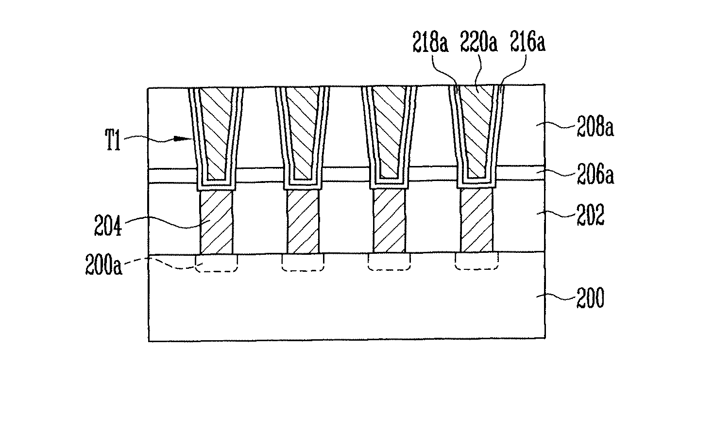
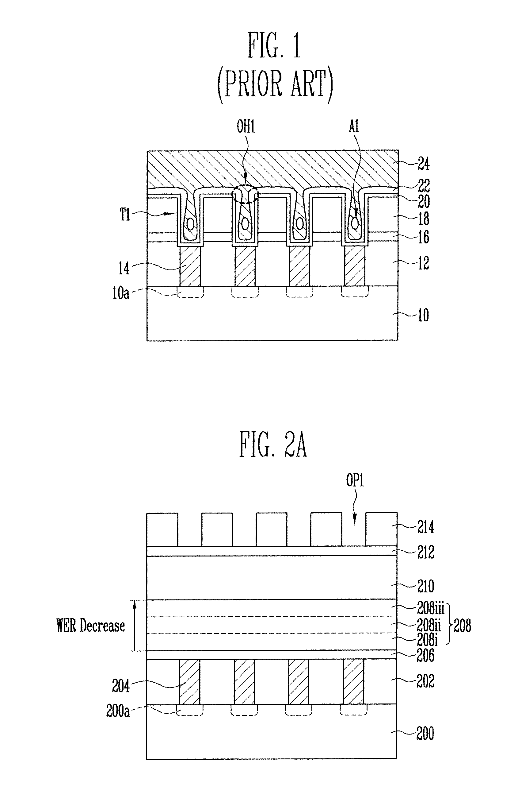
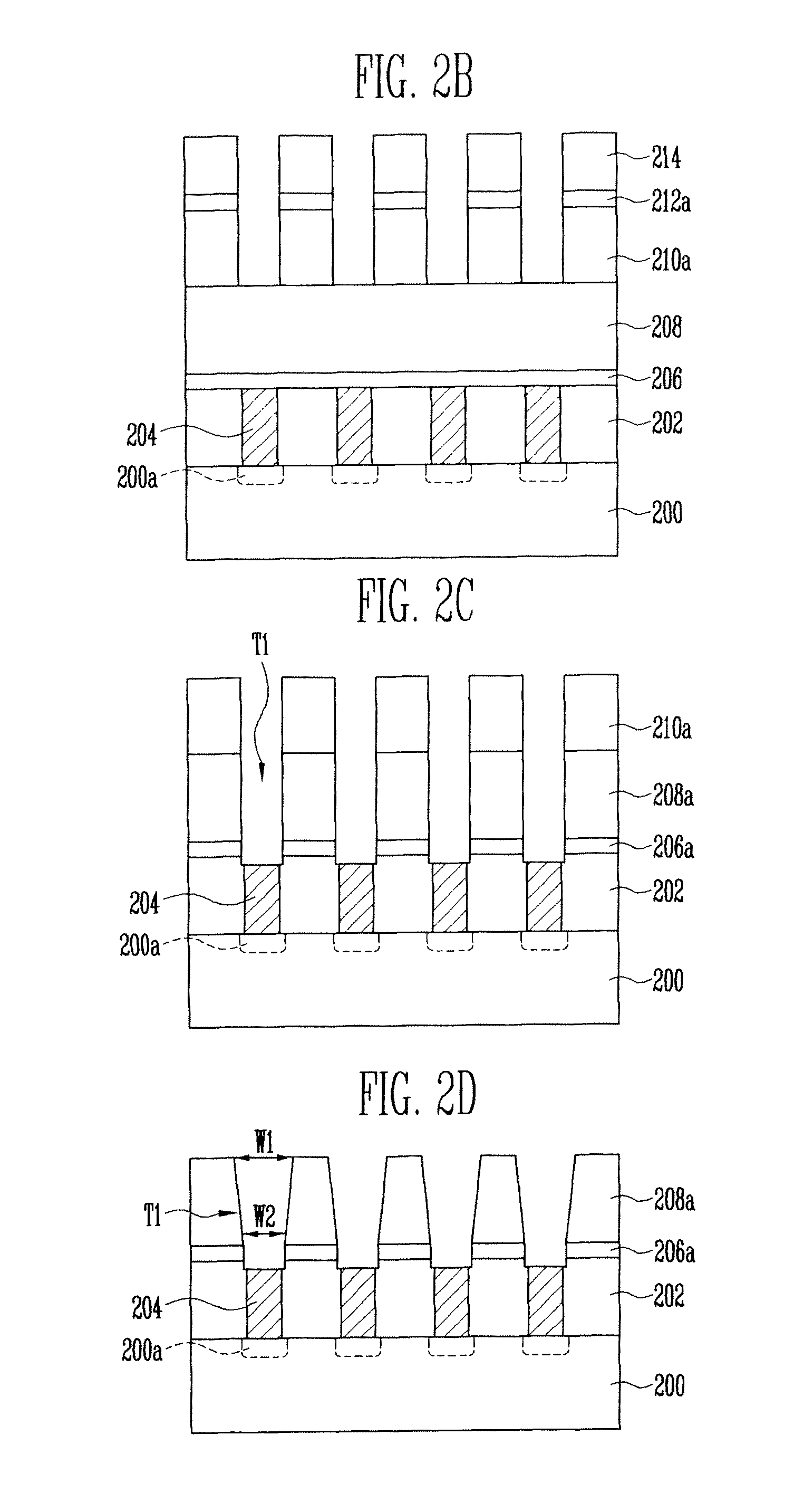
[0023]FIGS. 2A to 2G are cross-sectional views illustrating a method of manufacturing semiconductor devices according to an exemplary embodiment of this disclosure.

[0024]Referring to FIG. 2A, a first dielectric interlayer 202 and contact plugs 204 are formed over a semiconductor substrate 200 having junctions 200a formed therein. Preferably, the first dielectric interlayer 202 is formed on the semiconductor substrate 200. After contact holes are formed in the first dielectric interlayer 202 to expose the junctions 200a, the contact holes are filled with a metal material to form the contact plugs 204.

[0025]An etch-stop layer 206, a second dielectric interlayer 208, a hard mask layer 210, and a bottom anti-reflective co...


PUM


Abstract

A method of manufacturing semiconductor devices includes forming a dielectric interlayer over a semiconductor substrate, wherein a wet etch rate (WER) is faster in an upper part of the dielectric interlayer than in a lower part of the dielectric interlayer, forming trenches in the dielectric interlayer, performing a cleaning process to make a width of an opening portion in an upper part of each of the trenches wider than a width of an opening portion in lower part of the trench, and filling the trenches with a metal layer.

Description

CROSS-REFERENCE TO RELATED APPLICATION[0001]Priority to Korean patent application number 10-2010-0038960 filed on Apr. 27, 2010, the entire disclosure of which is incorporated by reference herein, is claimed.BACKGROUND[0002]An exemplary embodiment relates generally to a method of manufacturing semiconductor devices and, more particularly, to a method of manufacturing semiconductor devices in which a gap-fill process can be easily performed.[0003]A semiconductor device typically includes a number of gates and metal lines.[0004]To form the gates or metal lines, a gap-fill process of filling contact holes or trenches with a material to be formed within the contact holes or trenches may be used. Meanwhile, with an increase in the degree of integration of semiconductor devices, the intervals between the gates and between the metal lines and the width thereof are narrowed. Accordingly, a void or seam is generated within the contact hole or the trench, making it gradually more difficult to...

Claims


Application Information

Patent Timeline
Patent Type & Authority Patents(United States)
IPC IPC(8): H01L21/4763
CPCH01L21/76822H01L21/76804
Inventor KIM, SANG DEOK
Owner SK HYNIX INC
Why Eureka
Try Eureka