Conducting wire for electric machine

a technology of conducting wire and electric machine, which is applied in the direction of windings, dynamo-electric components, and magnetic circuit shapes/forms/construction, etc., can solve the problems of reducing the core reducing the effective alternating current resistance at higher speeds and/or frequencies, etc., to improve the heat dissipation of the conducting wire, reduce the effective alternating current resistance, and increase the surface area

Active Publication Date: 2012-10-23
GM GLOBAL TECH OPERATIONS LLC
View PDF7 Cites 0 Cited by
  • Summary
  • Abstract
  • Description
  • Claims
  • Application Information

AI Technical Summary

Benefits of technology

[0008]Accordingly, the concave depression in each of the first side and the second side of the conducting wire increases the surface area of the conducting wire, which improves the heat dissipation of the conducting wire. Additionally, the concave depression in each of the first side and the second side of the conducting wire increases a skin depth of the conducting wire, i.e., the primary current carrying portion of the conducting wire, and reduces the core of the conducting wire, i.e., the non-current carrying portion of the conducting wire, which reduces the effective alternating current resistance at higher speeds and / or frequencies.

Problems solved by technology

Additionally, the concave depression in each of the first side and the second side of the conducting wire increases a skin depth of the conducting wire, i.e., the primary current carrying portion of the conducting wire, and reduces the core of the conducting wire, i.e., the non-current carrying portion of the conducting wire, which reduces the effective alternating current resistance at higher speeds and / or frequencies.

Method used


Image

  • Conducting wire for electric machine
  • Conducting wire for electric machine
  • Conducting wire for electric machine

Examples


Embodiment Construction

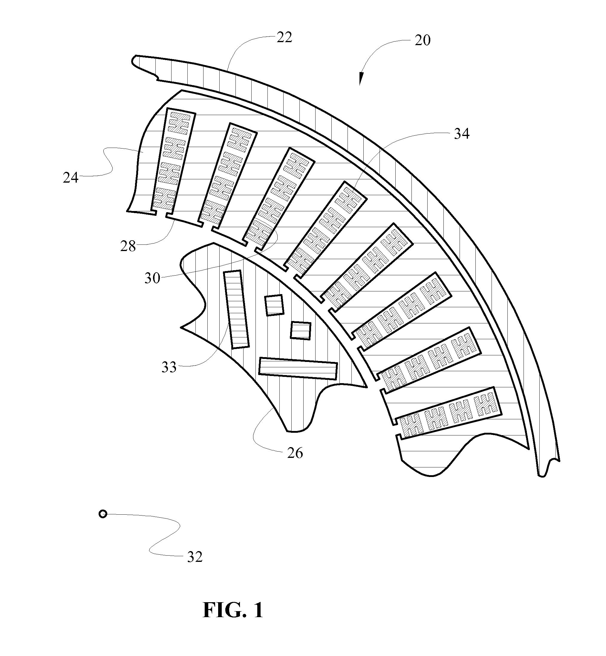
[0013]Referring to the Figures, wherein like numerals indicate corresponding parts throughout the several views, an electric machine is shown generally at 20 in FIG. 1. The electric machine 20 may include an electric motor configured for converting an electric current into mechanical motion, an electric generator configured for converting mechanical motion into an electric current, or some other similar device.

[0014]Referring to FIG. 1, the electric machine 20 includes a housing 22, a stator 24 and a rotor 26. The stator 24 is fixedly coupled to the housing 22. The stator 24 includes an interior circumferential surface 28, and defines a plurality of slots 30. The slots 30 extend radially outward from the interior circumferential surface 28 into the stator 24. The rotor 26 opposes the stator 24 and is rotatably coupled to the housing 22. The rotor 26 is rotatable about a longitudinal axis 32 relative to the stator 24, and includes a plurality of magnets 33 as is well known. The elect...


PUM


Abstract

A conducting wire for a stator of an electric machine includes a cross section having a first side, a second side, a third side and a fourth side. The third side and the fourth side are parallel with each other, with the first side and the second side extending between the third side and the fourth side. The first side and the second side each define a concave depression.

Description

TECHNICAL FIELD[0001]The invention generally relates to an electric machine, and more specifically to a conducting wire for a stator of the electric machine.BACKGROUND OF THE INVENTION[0002]Electric machines, such as an electric motor, include a stator and a rotor having opposing surfaces. The stator includes a plurality of slots disposed on a surface of the stator, and a plurality of conducting wires disposed within the slots of the stator. The rotor is rotatable about an axis relative to the stator. The conducting wires generate an electromagnetic force in response to an electric current passing therethrough. The electromagnetic force acts against the rotor to cause the rotor to rotate relative to the stator.[0003]The current density varies throughout the conducting wire based on frequency and due to the presence of magnetic fields. Typically, the majority of the current is conducted through the outer surface region of the conducting wire, commonly referred to as the “skin depth” ...

Claims


Application Information

Patent Timeline
Patent Type & Authority Patents(United States)
IPC IPC(8): H02K3/04
CPCH02K3/12H02K1/16H02K3/18
Inventor SAVAGIAN, PETER J.VYAS, RAJEEV
Owner GM GLOBAL TECH OPERATIONS LLC
Why Eureka
Try Eureka