Image forming apparatus, belt unit, and belt driving control method

a technology of image forming apparatus and belt drive, which is applied in the direction of electrographic process apparatus, instruments, optics, etc., can solve the problems of uneven thickness, fluctuation of travel velocity, and uneven alignment of different color images in multicolor images

Inactive Publication Date: 2012-10-23
RICOH KK
View PDF27 Cites 36 Cited by
  • Summary
  • Abstract
  • Description
  • Claims
  • Application Information

AI Technical Summary

Benefits of technology

[0042]In view of the foregoing, in one illustrative embodiment of the present invention, a belt unit includes a belt configured to travel rotationally and looped around at least two rotary support members, a driven rotary member disposed facing at least one of the rotary support members via the belt and configured to rotate with the belt, and a controller. The controller minimizes fluctuation in one of a travel velocity and a travel distance of the belt by controlling the travel of the belt based on one of a rotational angular displacement and a rotational angular velocity of each of the rotary support member and the driven rotary member.
[0044]Yet another illustrative embodiment of the present invention describes a method of controlling a belt looped around at least two rotary support members. The method includes detecting one of a rotational angular displacement and a rotational angular velocity of one of the rotary support members and a driven rotary member disposed facing one of the rotary support member via the belt and configured to rotate with the belt, evaluating rotational fluctuation information regarding a time period required for the belt to make at least one rotation, extracting AC components whose periods respectively correspond to one rotation of the rotary support member and the driven rotary member and are different from each other from the rotational fluctuation information, evaluating a fluctuation component caused by the belt by deducting the Ac components from the rotational fluctuation information, and minimizing fluctuation in one of a travel velocity and a travel distance of the belt by controlling travel of the belt based on the fluctuation component caused by the belt and the AC components.

Problems solved by technology

In the image forming apparatuses described above, it is necessary to control travel of such movable belts accurately in order to prevent image failure such as color deviation, which means that the different color images are not properly aligned in the multicolor image.
For example, when a belt is produced through centrifugal burning using a cylindrical mold, its thickness may be uneven.
If the thickness of the belt is uneven, the belt moves faster when its thicker portion is on a driving roller and slower when its thinner portion is on the driving roller, thus causing its travel velocity to fluctuate.
However, in the method using the belt thickness profile, a belt thickness measurement process is required, which increases the production cost.
Further, in the method using the detection pattern, consumption of toner is relatively high because the detection pattern is formed on the entire circumference of the belt.
Moreover, in the method using the AC component of the rotational angular displacement or rotational angular velocity of the driven rotary member, although the belt thickness fluctuation is approximated by a sine function or a cosine function, approximating the belt thickness fluctuation to a periodic function is difficult.

Method used


Image

  • Image forming apparatus, belt unit, and belt driving control method
  • Image forming apparatus, belt unit, and belt driving control method
  • Image forming apparatus, belt unit, and belt driving control method

Examples


Embodiment Construction

[0065]In describing preferred embodiments illustrated in the drawings, specific terminology is employed for the sake of clarity. However, the disclosure of this patent specification is not intended to be limited to the specific terminology so selected and it is to be understood that each specific element includes all technical equivalents that operate in a similar manner and achieve a similar result.

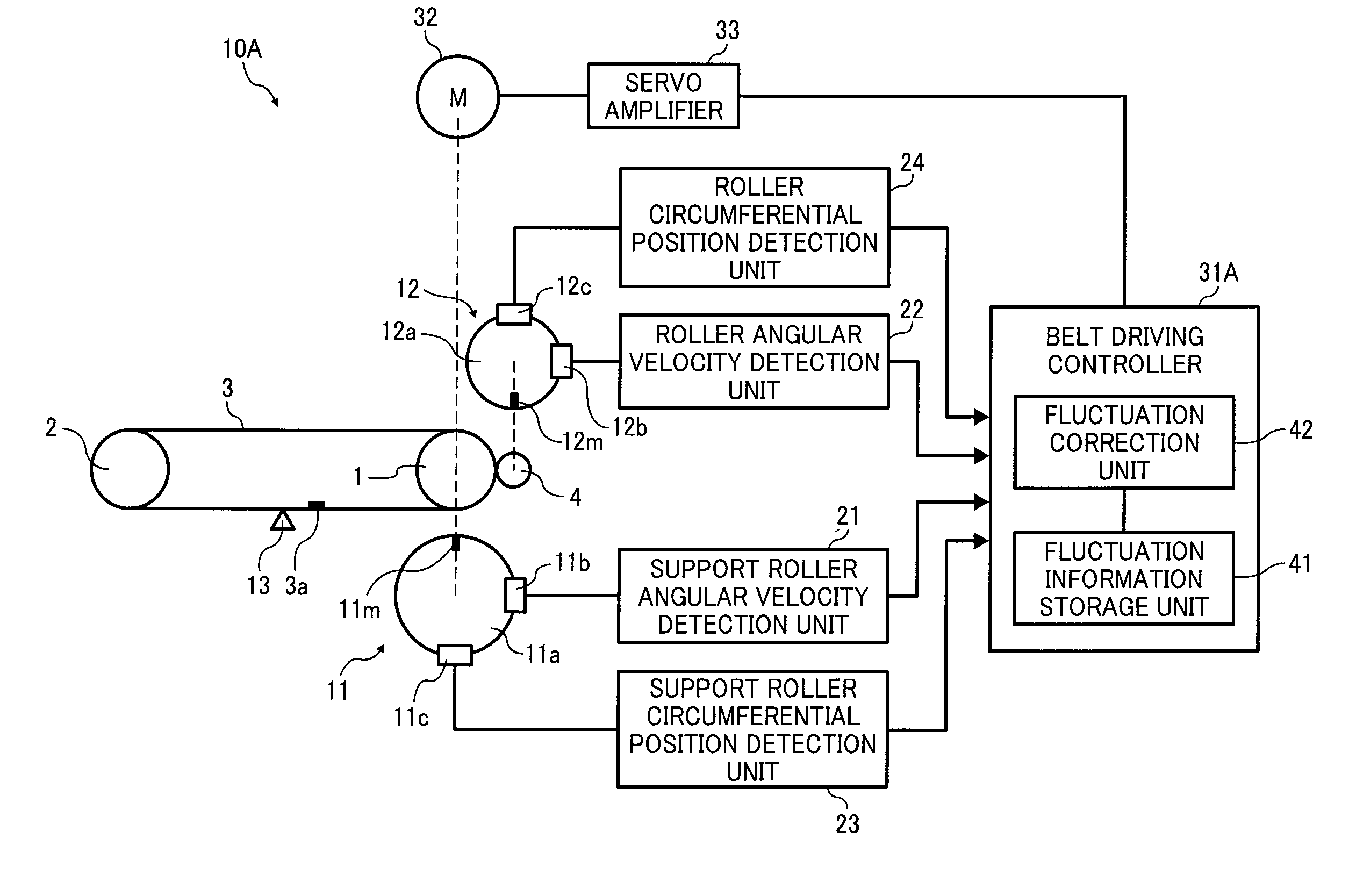
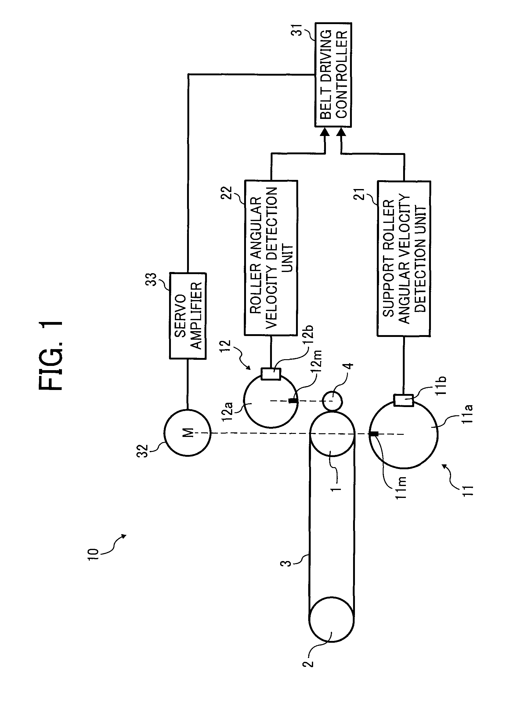
[0066]Referring now to the drawings, wherein like reference numerals designate identical or corresponding parts throughout the several views thereof, and particularly to FIGS. 1 and 2, a belt unit 10 according to an illustrative embodiment of the present invention is described.

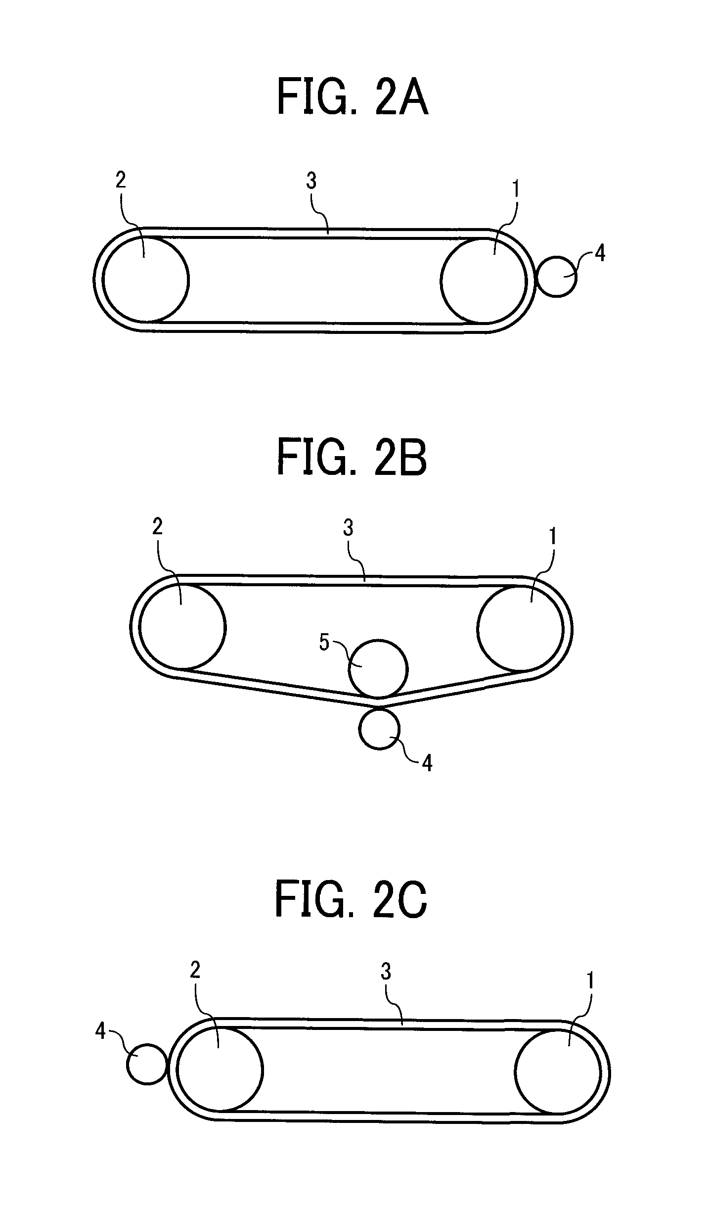
[0067]FIG. 1 illustrates the belt unit 10, FIG. 2A illustrates a belt driving mechanism of the belt unit 10 shown FIG. 1, and FIGS. 2B and 2C illustrate different examples of the belt driving mechanism.

[0068]Referring to FIGS. 1 and 2A, the belt unit 10 includes a first roller 1 and a second roller 2 both serving a...


PUM


Abstract

An image forming apparatus for forming an image on a recording medium includes a belt configured to travel rotationally and looped around at least two rotary support members, a driven rotary member disposed facing at least one of the rotary support members via the belt and configured to rotate with the belt, and a controller. The controller is configured to minimize fluctuation in one of a travel velocity and a travel distance of the belt by controlling the travel of the belt based on one of a rotational angular displacement and a rotational angular velocity of each of the rotary support member and the driven rotary member.

Description

BACKGROUND OF THE INVENTION[0001]1. Field of the Invention[0002]The present invention generally relates to an image forming apparatus and a belt unit.[0003]2. Discussion of the Background[0004]In general, an electrophotographic image forming apparatus, for example, a printer, a facsimile machine, a copier, a multifunction machine including at least two of these functions, etc., includes an image forming mechanism for forming an electrostatic latent image, developing the latent image with toner, and transferring the toner image onto a recording medium. The image forming apparatus further includes various movable belts including a photoreceptor belt, an intermediate transfer belt, a sheet transport belt, etc.[0005]It is to be noted that “image forming” includes both forming on a recording medium an image including a pattern, etc., that has no commonly understood meaning as well as an image including a letter and / or an illustration that does have a given meaning. Thus, printing, imagin...

Claims


Application Information

Patent Timeline
Patent Type & Authority Patents(United States)
IPC IPC(8): G03G15/00G03G15/01
CPCG03G15/0131G03G15/162G03G15/161G03G2215/0129G03G2215/0158
Inventor IMOTO, SHINJI
Owner RICOH KK
Why Eureka
Try Eureka