Piezoelectric vibrator, manufacturing method thereof, oscillator, electronic equipment, radio clock

a technology of piezoelectric vibrators and manufacturing methods, applied in the field of piezoelectric vibrators, can solve the problems of exceeding the prescribed value of piezoelectric vibrators, and achieve the effects of small fluctuation of resonance frequency, high accuracy, and sufficient electric characteristics

Inactive Publication Date: 2007-11-13
SII CRYSTAL TECH
View PDF6 Cites 22 Cited by
  • Summary
  • Abstract
  • Description
  • Claims
  • Application Information

AI Technical Summary

Benefits of technology

[0013]In view of the above-mentioned drawbacks, it is an object of the present invention to provide a piezoelectric vibrator which can sufficiently minimize the fluctuation of the oscillation frequency or the resonance resistance value even when a large static external force is applied to a package of the piezoelectric vibrator, a manufacturing method thereof, and an oscillator and en electronic equipment provided with the piezoelectric vibrator.
[0023]Further, different from a conventional case which performs bevel cutting after bonding, the cost incurred due to a loss by performing the bevel cutting using a lid or a base wafer as a unit product can be limited to a loss of the lid wafer or the base wafer as a single part and hence, it is possible to reduce the overall manufacturing cost.
[0024]The grooves which are preliminarily formed in the lid wafer or the base wafer have the V-shaped cross section and, in the full cutting step, the wafers are cut on the inclined surfaces of the V-shaped cross-sectional grooves along the direction of the V-shaped cross-sectional grooves. Accordingly, it is possible to provide the structure in which ridge portions of outer surfaces of individual products which are separated from each other are beveled. Due to such structure, it is possible to impart a profile shape which exhibits the favorable resistance to chipping attributed to an impact or the like. Further, it is also possible to set a thickness of a corrosion resistance film applied to the products uniformly.
[0025]Further, the soda-lime glass is used as the material of the lid wafer and the base wafer. The soda-lime glass is popularly used as a glass for display, exhibits the stable product quality and can be manufactured as a low cost. Accordingly, it is possible to manufacture the piezoelectric vibrators with a high yield and at a low cost. Further, the mirror polishing of the soda-lime glass can be performed easily and hence, the reduction of a thickness (lowering of height) of the vibrators as finished products by reducing a thickness of the soda-lime glass has the large degree of freedom compared to a method which uses a ceramic package of existing sizes.
[0027]Further, when the above-mentioned piezoelectric vibrators are connected to the integrated circuits or clock portions of portable equipments as the oscillators and, further, when the piezoelectric vibrators are connected to filter portions of the radio clocks, the piezoelectric vibrators of the present invention exhibit the extremely small fluctuation of the resonance frequency and the resonance resistance value attributed to the influence of an external force. That is, the piezoelectric vibrators exhibit the sufficient electric characteristics of the vibrators against a tension or a compression force attributed to an ambient temperature change cycle applied to the vibrators after the piezoelectric vibrators are mounted on a board. Accordingly, it is possible to maintain the oscillators, the electronic equipments or the radio clocks at high accuracy over a long period.

Problems solved by technology

However, when the withstanding pressure characteristic of the completed piezoelectric vibrators which are manufactured in accordance with the flow of the conventional manufacturing method are checked, it has been found that some piezoelectric vibrators exhibit the fluctuation which exceeds a prescribed value.

Method used


Image

  • Piezoelectric vibrator, manufacturing method thereof, oscillator, electronic equipment, radio clock
  • Piezoelectric vibrator, manufacturing method thereof, oscillator, electronic equipment, radio clock
  • Piezoelectric vibrator, manufacturing method thereof, oscillator, electronic equipment, radio clock

Examples


embodiment 1

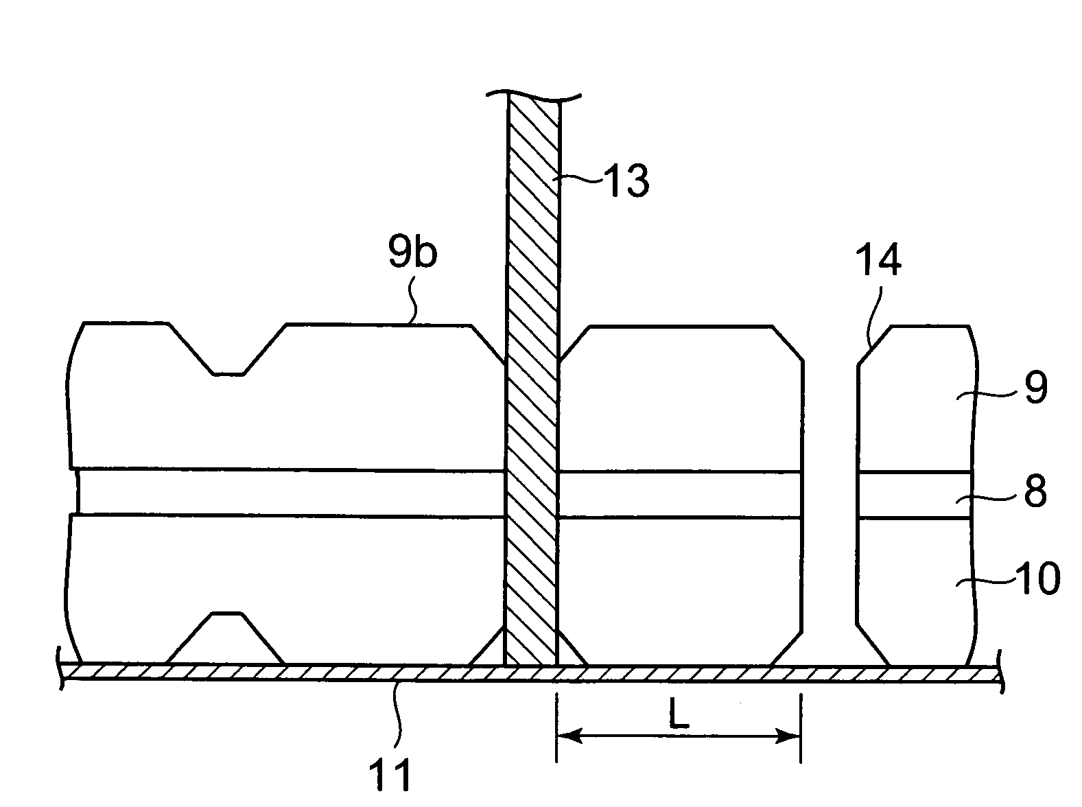
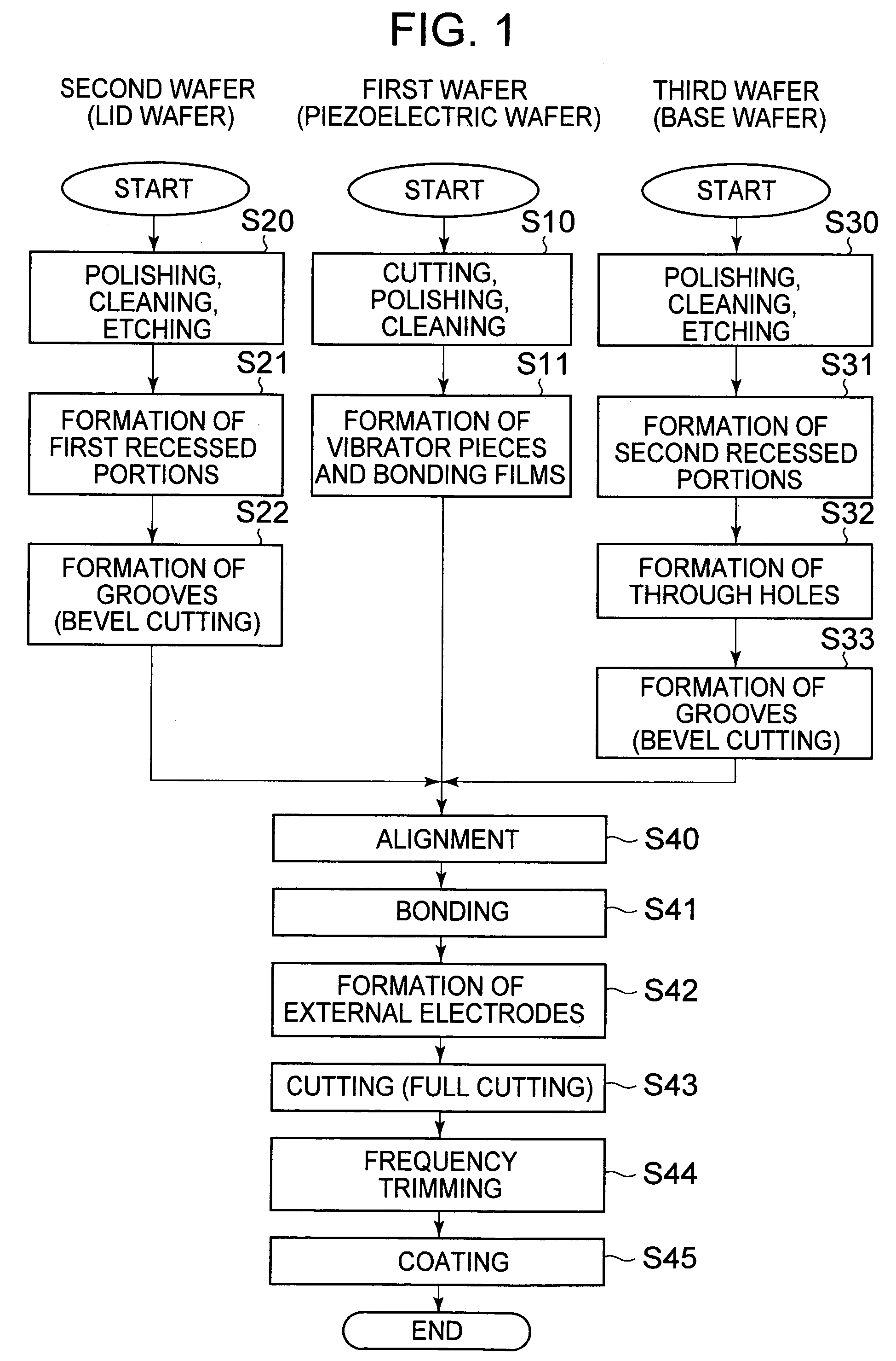
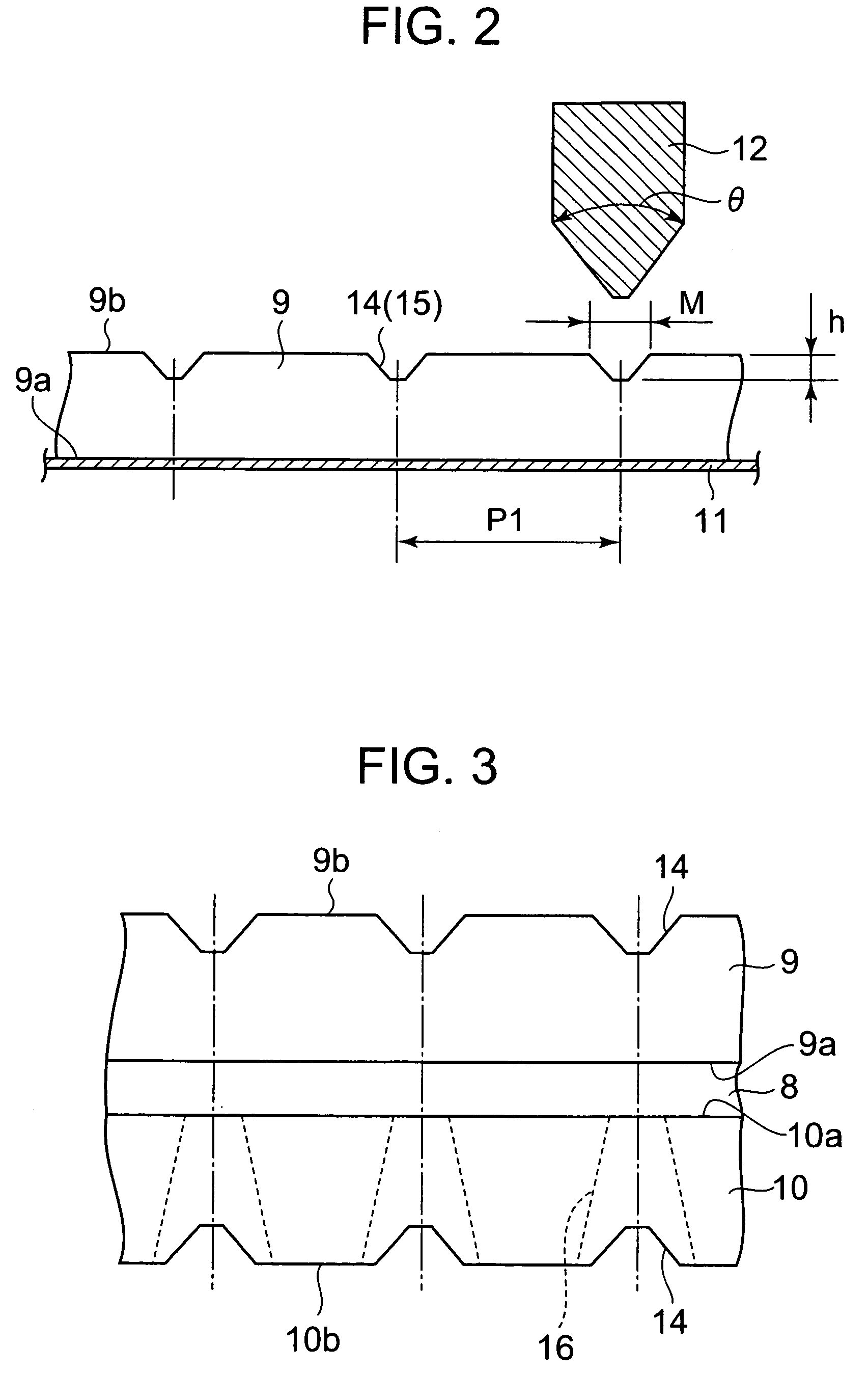
[0040]A first embodiment of a manufacturing method of piezoelectric vibrators according to the present invention is explained in accordance with a manufacturing step flow chart shown in FIG. 1 and step charts shown in FIG. 2 to FIG. 4. Numerals indicating the constitutions are explained also in conjunction with an example of the piezoelectric vibrator shown in FIG. 5.

[0041]In this embodiment, the explanation will be made with respect to an example in which quartz crystal is used as a piezoelectric material and a tuning fork type is used as a shape of vibrator pieces. Further, although the explanation will be made with respect to a case in which wafers for forming a lid and a base are respectively prepared using soda-lime glass, the selection of the piezoelectric material and the respective materials of the lid and base may adopt the combination of quartz crystal and a material other than glass. Further, although a result of an experiment using samples in which a thickness of the qua...

embodiment 2

[0072]As a second embodiment of the present invention, an oscillator in which the above-mentioned piezoelectric vibrator is connected to an integrated circuit as an oscillator is explained in conjunction with FIG. 7.

[0073]FIG. 7 is a rough schematic view showing the constitution of a tuning-fork-type-quartz crystal oscillator and is a plan view showing a surface-mounting-type piezoelectric vibrator which makes use of the above-mentioned tuning-fork-type quartz crystal vibrator according to the present invention.

[0074]In FIG. 7, the tuning-fork-type quartz crystal vibrator 51 is set at a given position on a board 52, while an integrated circuit for oscillator indicated by numeral 53 is arranged close to the quartz crystal vibrator. Further, an electronic component 54 such as a capacitor is also mounted on the board 52. These respective parts are electrically connected with each other through a wiring pattern not shown in the drawing. The mechanical vibrations of a piezoelectric vibra...

embodiment 3

[0076]As a third embodiment of the present invention, an electronic equipment used in a state that the above-mentioned piezoelectric vibrator is connected to a clock part is explained in conjunction with FIG. 8. As an example of the electronic equipment, a preferred embodiment on a portable information equipment represented by a mobile phone is explained in detail.

[0077]First of all, as a premise, the portable information equipment according to this embodiment is a development or an improvement of a wrist watch of the related art. The portable information equipment resembles the wrist watch in appearance, arranges a liquid crystal display on a portion thereof which corresponds to a dial plate, and can display a current time and the like on a screen of the display. In using the portable information equipment as a communication device, the portable information equipment is removed from a wrist and a user can perform the communication in the same manner as a mobile phone of the related...


PUM

PropertyMeasurementUnit
thicknessesaaaaaaaaaa
diameteraaaaaaaaaa

Abstract

A piezoelectric vibrator has a vibrator piece and a frame integral with the vibrator piece. The frame is connected to one end of and surrounds the vibrator piece. A lid has a surface anodically bonded to a first surface of the frame. The lid has a recessed portion at a position disposed opposite to and confronting the vibrator piece. A base has a surface anodically bonded to a second surface of the frame opposite the first surface thereof. The base has a recessed portion at a position disposed opposite to and confronting the vibrator piece. A beveled portion is formed around a surface of one of the lid and the base which does not correspond to the anodically bonded surface thereof.

Description

BACKGROUND OF THE INVENTION[0001]1. Field of the Invention[0002]The present invention relates to a piezoelectric vibrator, a manufacturing method thereof, and an oscillator, an electronic equipment or a radio clock which includes the piezoelectric vibrator.[0003]2. Description of the Related Art[0004]In mobile phones and personal information terminal equipments, a large number of piezoelectric vibrators are used as timing sources of control signals, reference signal sources, clock sources and the like. A large number of structures of the piezoelectric vibrators adopt a mode in which a vibrator piece is fixedly secured in the inside of a base formed of a box-like ceramic package using a conductive adhesive agent or a mode in which a vibrator piece is fixedly secured in the inside of a hermetic vessel of a cylinder type by solder plating. Along with the further miniaturization of the vibrator, it becomes difficult to accurately mount a vibrator piece on a holder such as a base or a pl...

Claims


Application Information

Patent Timeline
Patent Type & Authority Patents(United States)
IPC IPC(8): H01L41/053G04G5/00G04R20/00H01L41/09H01L41/18H01L41/22H01L41/312H01L41/338H03B5/32H03H3/02H03H9/02
CPCH03B5/32H03H3/02H03H9/0542H03H9/1035H03H9/215H03H9/0595Y10T29/42
Inventor OOUCHI, KEIICHIYOSHIDA, SUSUMUYAMANE, SHUJI
Owner SII CRYSTAL TECH
Why Eureka
Try Eureka