Optical tomograph

a tomograph and optical technology, applied in the field of optical tomographs, can solve the problems of difficult to achieve the resolution increase in the depth direction orthogonal to the optical axis, the inability to optimally maintain the focus state of the emitted light directed to the observation object over the entire area of the tomograph, and the inability to adjust the depth direction easily, etc., to achieve the effect of stable characteristics, high resolution and contras

Inactive Publication Date: 2008-05-01
KOWA CO LTD
View PDF4 Cites 23 Cited by
  • Summary
  • Abstract
  • Description
  • Claims
  • Application Information

AI Technical Summary

Benefits of technology

[0022]A suitable wavelength can be selected from among light sources whose wavelengths differ in accordance with the type of object, and an image having a higher resolution and contrast can therefore be obtained.
[0023]Light-modulation means, movement means, and sweeping means are all provided in the probe optical path for the object. Therefore, the optical system can be easily adjusted, mechanical movement errors have little effect on the interferometer, and stable characteristics can be maintained.
[0024]Even if the light beam is moved in the direction of the optical axis, a match will be maintained between the length of the optical path of the probe light up to the object focal point and the length of the optical path of the reference light up to the fixed reflective surface. Therefore, fluctuations in the detection efficiency of the interference signal can be minimized, and a high-contrast image at a high resolution can be obtained.
[0025]Point-type high-efficiency, high-sensitivity devices can be used for the light source and detector. Therefore, a highly dependable, practical, and economical optical tomograph can be provided by completely eliminating special parts from other main optical components within the optical path and completing the device in a relatively inexpensive manner.

Problems solved by technology

However, the configurations disclosed in Japanese Laid-open PCT Application 1994-511312 and in Japanese Laid-open Patent Applications 1992-174345, 2000-126188, 1996-206075, and 1998-332329 have a problem in that the focus state of the emitted light (sample light) directed to the observation object cannot be optimally maintained over the entire area of the tomographic picture, and the increase in the resolution in an in-plane direction orthogonal to the optical axis (depth direction) is also difficult to achieve due to the fact that the observation object is scanned in the depth direction by controlling the movement of the reflective mirror in the direction of the optical axis in relation to the reference light.
Additionally, the configuration disclosed in Japanese Laid-open Patent Application 1996-206075 has a problem in that the mechanism for the length / depthwise scanning of an object in the direction of the optical axis is disposed in the reference optical path so that the interferometer itself is readily subjected to the effects of vibration and mechanical feed errors, and the interference function is therefore readily affected by factors such as the axial wobbling of the rotating helical mirror that is used in scanning in the direction of the optical axis.
Furthermore, the configuration disclosed in Japanese Laid-open Patent Application 1998-332329 has a problem in that a special semiconductor laser light source that can stably control the frequency of light over a desired range is necessary, that light sources of this type are limited in variety and wavelength, and that the light sources themselves are expensive.
In addition, when a one- or two-dimensional image pickup device is used as a detector, it becomes difficult to sufficiently reduce the size of the space filter disposed in the preceding optical path, and it is also difficult to completely remove unnecessary stray light from the sample.
Yet further, the configuration disclosed in Japanese Laid-open Patent Application 2003-93346 has a problem in that, although the resolution can be increased because the emitted light is focused on a predetermined portion of the object (eye to be examined) by the movement of the two mirrors, the effects of stray light and the like become pronounced due to the fact that spatial data is simultaneously detected at multiple points, making it difficult to improve the SN (signal to noise ratio) of the image.
However, although it is a common opinion that using an optical fiber gives flexibility in arranging the optical path, there is a problem in that the precision optics and mechanical components for linking to the optical fiber are expensive.
Even further, in Japanese Laid-open Patent Applications 1998-332329 and 2003-93346, there is a problem in that the one- or two-dimensional image pickup device that is used to detect interference signals has low sensitivity when compared to a point-type optical detector such as a photomultiplier, and imparting higher sensitivity to the image pickup device is expensive.

Method used


Image

  • Optical tomograph
  • Optical tomograph
  • Optical tomograph

Examples


Embodiment Construction

[0031]The invention will now be described in detail with reference to the embodiments shown in the drawings.

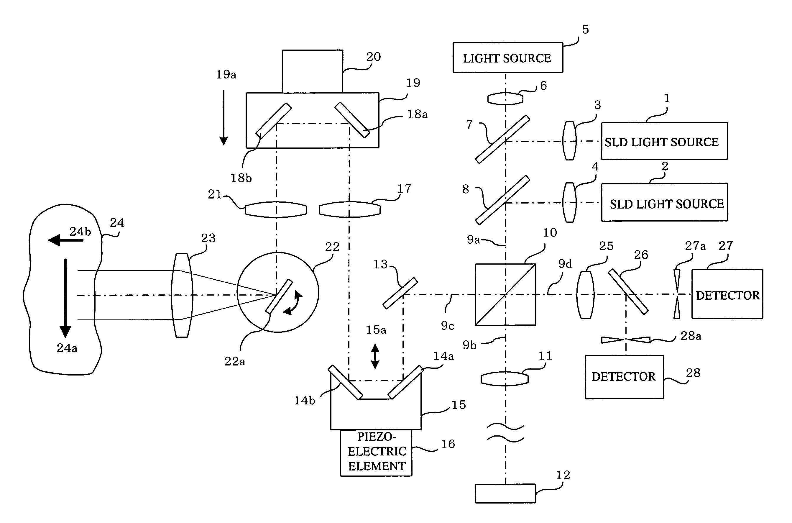
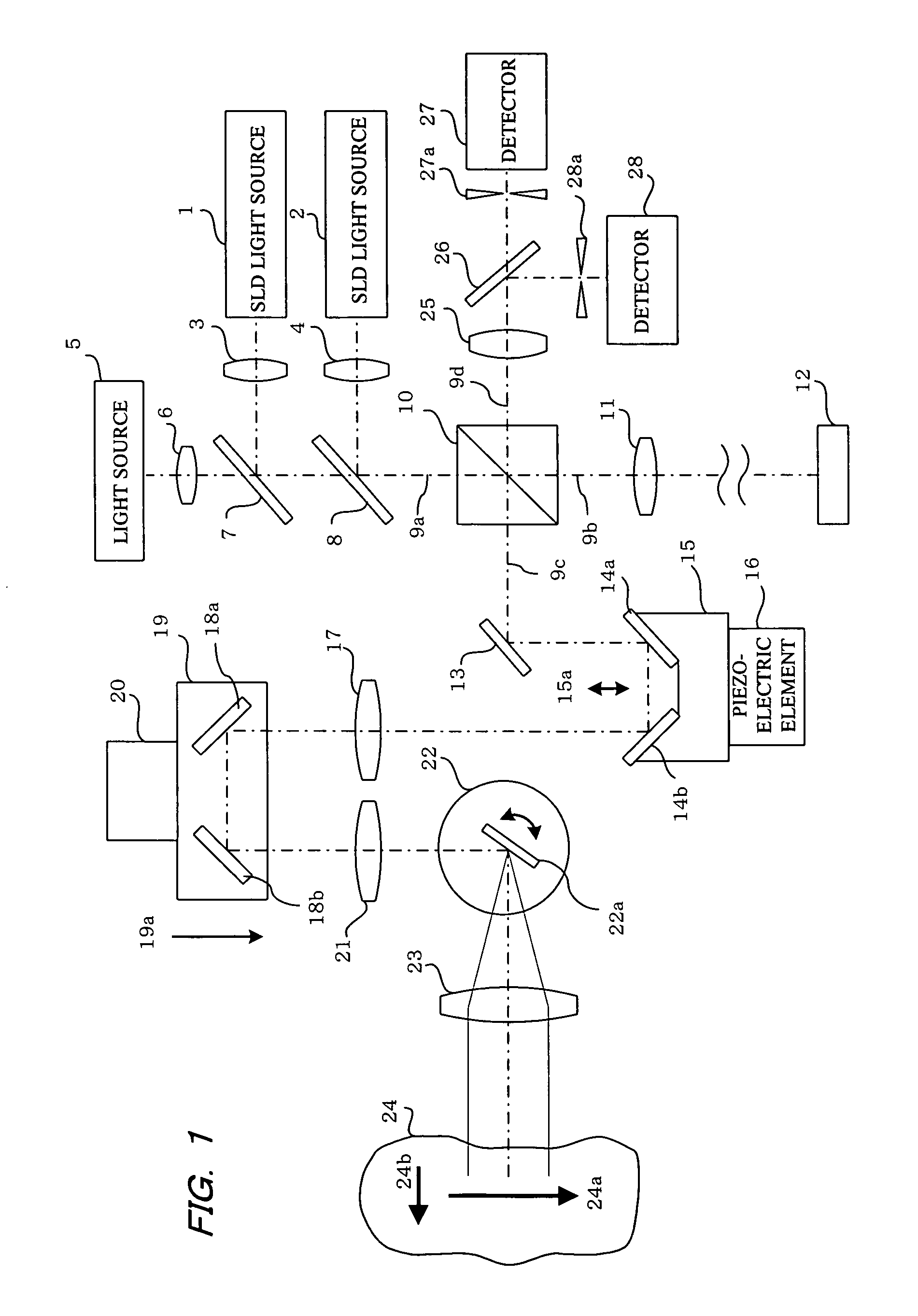
[0032]In FIG. 1, the objects indicated by reference numerals 1 and 2 are super luminescent diodes (SLD) for emitting partially coherent light. These diodes are light sources for generating a light beam that has low interference (little interference), which is necessary in observing a tomographic picture. The diodes emit light in different near-infrared (invisible) wavebands having emission wavelengths of, e.g., 1300 nm and 850 nm, respectively, and the light beams emitted from the light sources 1 and 2 are collimated by lenses 3 and 4, respectively.

[0033]In FIG. 1, an additional light source 5 is provided. This light source is a semiconductor laser for emitting red (visible) light having a wavelength of 670 nm, for example. The light source 5 is provided for the sake of convenience in order to verify the optical path of the beams from the invisible-light sources 1 and 2 by usi...


PUM


Abstract

A partially coherent light beam from a light source is split between a probe light beam toward an observation object and a reference light beam toward a fixed reflective surface. The frequency of the probe light beam is shifted by optical-modulation means. The probe light beam whose frequency has been shifted is swept in a direction of an optical axis and in a direction orthogonal thereto to scan the object two-dimensionally. Reflected light beam from the object is combined with the reference light beam to generate interference light. A detector receives a time-based interference signal from the interference light obtained from the movement of the probe light beam in the direction of the optical axis and the sweeping in the direction orthogonal to the optical axis to derive therefrom reflection intensity data of the object. In such a configuration, the mechanically moving portion is disposed in the probe optical path. Therefore, changes in the interference characteristics of the light that accompany the mechanical scanning are less likely to occur and optical adjustments are also made easy.

Description

BACKGROUND OF THE INVENTION[0001]1. Field of the Invention[0002]The present invention relates to an optical tomograph, and more specifically relates to an optical tomograph for obtaining tomographic imaging data of an observation object by sweeping a light beam from a light source to scan a prescribed region of the object, and detecting and processing reflected light from the object by using optical interference.[0003]2. Description of the Prior Art[0004]In prior art, a device for imaging tomographic data (optical coherence tomography: OCT) of an observation object by using the interference of a low-interference light beam (partially coherent light) can create and display an arbitrary tomographic image of an observation object in a noncontact, noninvasive manner. Therefore, optical tomographs are particularly useful in medical imaging and are beginning to be used in general clinical examinations in ophthalmology, as well as in dermatological diagnoses, endoscopic applications, and o...

Claims


Application Information

Patent Timeline
Patent Type & Authority Applications(United States)
IPC IPC(8): G01B11/02G01B9/02
CPCG01N21/4795G01B9/02003G01B9/02027G01B2290/45G01B9/02009G01B2290/65G01B9/02091
Inventor KOBAYASHI, KOJI
Owner KOWA CO LTD
Why Eureka
Try Eureka