Measuring instrument

a technology of measuring instruments and measuring axes, applied in the direction of measuring devices, mechanical roughness/irregularity measurements, instruments, etc., can solve the problems of tracking response, deterioration of the frequency characteristics of the swinging probe, and tracking respons

Active Publication Date: 2004-09-02
MITUTOYO CORP
View PDF10 Cites 24 Cited by
  • Summary
  • Abstract
  • Description
  • Claims
  • Application Information

AI Technical Summary

Problems solved by technology

However, according to the measuring instrument described in the Japanese Utility Model Registration No. 2556550, the inertia of the entire arm is increased on account of the motor provided on the arm, so that the frequency characteristics of the swinging probe may be deteriorated, which may result in deterioration in the swingability of the arm.
Accordingly, tracking response to minute irregularities on the workpiece surface may be deteriorated, and when the scanning speed for moving the probe along the workpiece surface, i.e. moving speed of the probe relative to the workpiece surface is accelerated, measurement accuracy may be deteriorated.
Therefore, it is difficult to increase the scanning speed and the measurement efficiency may not be improved.
Further, since the the entire arm bears great inertia, when the probe is scanned along the workpiece surface, excessive measuring force in the scanning direction (i.e. pressing force of the probe against the workpiece in the scanning direction) may be applied, so that the workpiece surface and the probe may be damaged.
Accordingly, a complicated wiring without applying disturbance on the arm is required, so that it is difficult to improve the productivity.
Further, desired measuring force may not be obtained on account of the snapping of the wire caused by repeatedly applying a load on the wiring by the swinging movement of the arm.
In order to improve the accuracy of the measurement, the coil of the arm is required to linearly move in the axial direction relative to the magnetic component, however, it is difficult to convert the arc movement of the coil of the arm into a linear movement solely by the arrangement of the voice coil motor.
Accordingly, the arc movement has to be corrected as a linear movement, which requires an additional circuitry for the linear conversion, so that the structure of the instrument becomes complicated and productivity improvement and cost reduction are difficult to be achieved.
As described above, in the measuring instrument disclosed in the Japanese Utility Model Registration No. 2556550, the inertia of the arm is increased on account of the presence of the motor for moving the weight for keeping the constant measuring force and the tracking response of the probe relative to the irregularities on the workpiece surface is deteriorated, so that the measurement efficiency cannot be improved on account of the difficulty in increasing the scanning speed of the probe and the workpiece surface may be damaged by the probe.
In the measuring device disclosed in the Japanese Patent Laid-Open Publication No. 05-340706, the wiring of the voice coil motor for keeping the constant measuring force may influence on the swing movement of the arm and the design without being influenced by the wiring is difficult.
Further, a circuitry for converting the arc movement in the voice coil motor into a linear movement is required and the productivity may not be improved.
In the measuring instrument disclosed in the Japanese Patent Laid-Open Publication No. 2000-111334, it is difficult to calculate and input the command value for setting the driving condition of the measuring force adjuster for keeping a constant measuring force and improvement in the productivity is desired.

Method used


Image

  • Measuring instrument
  • Measuring instrument
  • Measuring instrument

Examples


Embodiment Construction

)

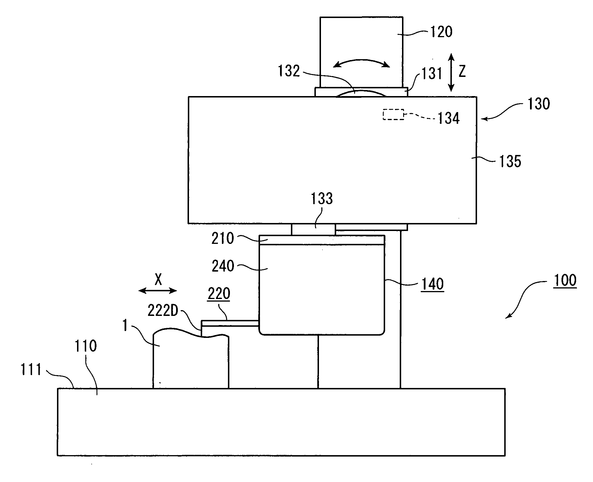
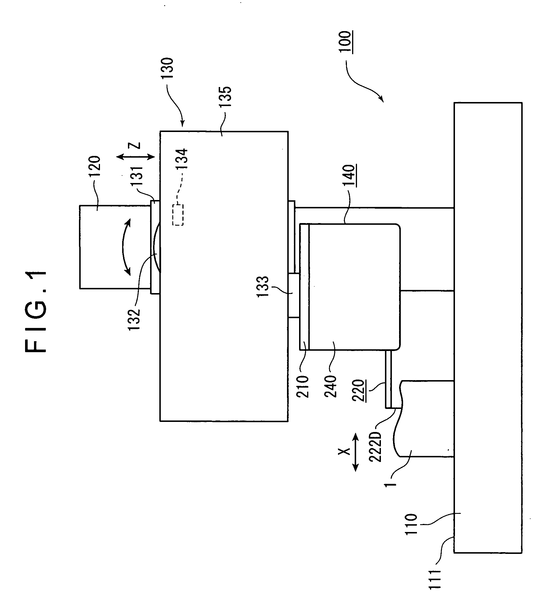
[0032] An arrangement of a measuring instrument according to an embodiment of the present invention will be described below with reference to attached drawings. Incidentally, though a surface-tracking measuring instrument will be described in the present embodiment, the present invention may be applied to other type of measuring instrument. FIG. 1 is a schematic illustration showing an outline of the measuring instrument. FIG. 2 is a schematic illustration showing an outline of the body of the measuring instrument. FIG. 3 is an illustration showing how the measuring instrument works. FIG. 4 is an illustration showing the centroid position of an arm.

[0033] (Structure of Measuring Instrument)

[0034] In FIG. 1, 100 denotes a measuring instrument, the measuring instrument 100 being a surface-tracking measuring instrument for measuring a shape of a workpiece 1. The measuring instrument 100 has a base 110, a column 120, a moving section 130 and a body 140.

[0035] The base 110 is held and f...


PUM


Abstract

Centroid moments of components of an arm (220) are calculated based on three-dimensional model data and mass of the components, the centroid moments being combined to calculate a centroid position (G) of the entirety of the arm (220). The arm (220) is adjusted and swingably supported so that a stylus (222D) provided on an end of the arm (220) being swingably supported by a support (210) that moves relative to a workpiece (1) touches the workpiece (1) with a predetermined measuring force and the centroid position (G) is located on a horizontal plane including the fulcrum when the support (210) is inclined by an angle in the middle of an angle range within which the support (210) is rotated by a moving section (130). The measuring force is hardly fluctuated when the support (210) is inclined.

Description

[0001] 1. Field of the Invention[0002] The present invention relates to a measuring instrument that measures a swing movement of a swinging body when a probe of the swinging body touches a workpiece with a predetermined measuring force.[0003] 2. Description of Related Art[0004] Conventionally, measuring instruments for measuring a surface texture such as roughness, waviness, contour and roundness of a workpiece, e.g. surface roughness measuring instrument, contour measuring instrument and roundness measuring instrument, have been known. In such measuring instruments, a sensor scans the surface of the workpiece to collect scanning data, based on which the surface texture is obtained. The sensor includes a swingably supported arm having a probe to be in contact with the surface of the workpiece at a tip end thereof. In the conventional measuring instrument, the arm is swung according to the movement (displacement) of the probe in accordance with the irregularities on the workpiece sur...

Claims


Application Information

Patent Timeline
Patent Type & Authority Applications(United States)
IPC IPC(8): G01B5/20G01B5/28G01B21/20
CPCG01B5/28
Inventor HAMA, NOBUYUKIOKAMOTO, ICHIROUTANADA, HIDEO
Owner MITUTOYO CORP
Why Eureka
Try Eureka