Orthodontic bracket

a technology for orthodontic brackets and brackets, applied in the field of orthodontic brackets, can solve the problems of involute configuration, complex procedure for attaching and removing archwires, and inability to apply the pressor force over the necessary extent, so as to improve aesthetic appearance, less likelihood of residual food particles, and easy to carry out procedures for attaching and detaching

Inactive Publication Date: 2012-10-30
DENTSPLY SANKIN KK
View PDF5 Cites 31 Cited by
  • Summary
  • Abstract
  • Description
  • Claims
  • Application Information

AI Technical Summary

Benefits of technology

[0014]An object of the present invention is to provide an orthodontic bracket that employs a simple composition with slidable ligating means, is able to ligate an archwire by clamping, allows the archwire to be easily replaced with a different archwire, stably and reliably maintains dental arch and allows maintenance to be performed easily.
[0044]In the orthodontic bracket according to the present invention, the elastic force applied to the teeth by the archwire in cases of prominent crowding of teeth can be reduced, as a result of making contrivances in the portion of a slider through hole or in the manner in which the slider portion itself is used, while conversely, elastic action can be increased by adjusting the gap between the slot and arch wire. Moreover, since the materials of the bracket body and slider portion can be set according to their respective purpose of use, strength can be secured while simultaneously preventing wear of opposing teeth. In addition, the orthodontic bracket according to the present invention also gives advantages in clinical effectiveness in terms of aesthetic appearance, rapid progression of treatment, ease of manipulation and reduced risk and pain for the patient.

Problems solved by technology

In the case of a conventional ligating method using a ligature wire with wings or a ligating method that uses rubber bands through elastic deformation, pressing force exceeding necessary extent is inevitably applied and attachment and removal of the archwire requires a complex procedure.
In addition, conventional ligating members have a complex, involute configuration in which there are numerous irregularities in relation to the bracket.
Consequently, the structure of conventional brackets makes food particle, plaque and other foreign substances apt to remain on them, which is unsanitary.
In addition, these brackets also lacked aesthetic qualities.
However, a method in which a ligating member fits into wings from above the bracket to ligate the archwire in a groove in the bracket is a type of self-ligating method and the pressing force by the wire decreases due to the formation of gaps between the ligating member and wire.
Although this method facilitates the initial attachment procedure, the archwire must be repeatedly re-ligated during the course of orthodontic treatment and there is also a problem of the procedure requiring considerable complexity for the orthodontist in operation of attaching and detaching of the archwire.
In addition, this composition requires the ligating member to be detached during removal and, due to the extremely small size of the ligating member, there is a risk for the ligating member to fall off.
Moreover, since the wings have a protruding portion and the like, there is a problem where aesthetic characteristics are impaired from a Viewpoint of aesthetic appearance.
Although these integrated configurations facilitate the ligation and release procedures, they are all of the self-ligating types, hence they have irregularities with respect to their structure, thereby resulting in the shortcomings of inferior aesthetic properties and cleanability.
In these types of brackets in the prior art, the configurations thereof are not satisfactory in terms of providing orthodontic treatment.

Method used


Image

  • Orthodontic bracket
  • Orthodontic bracket
  • Orthodontic bracket

Examples


first embodiment

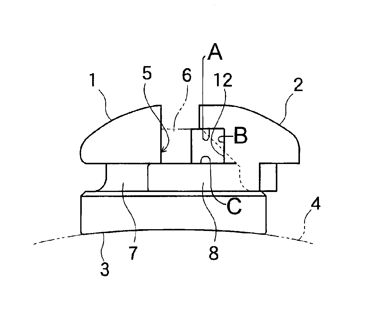
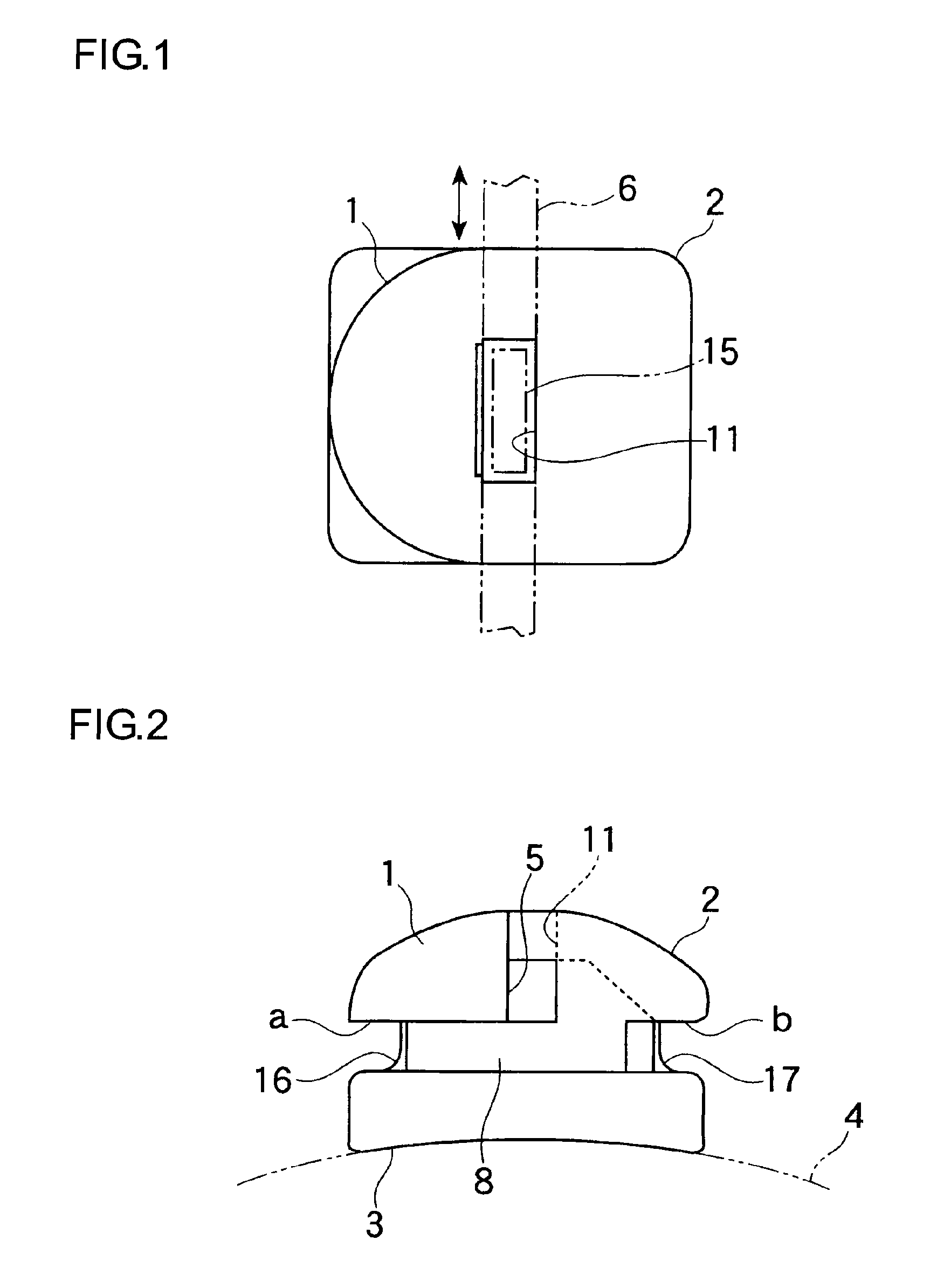
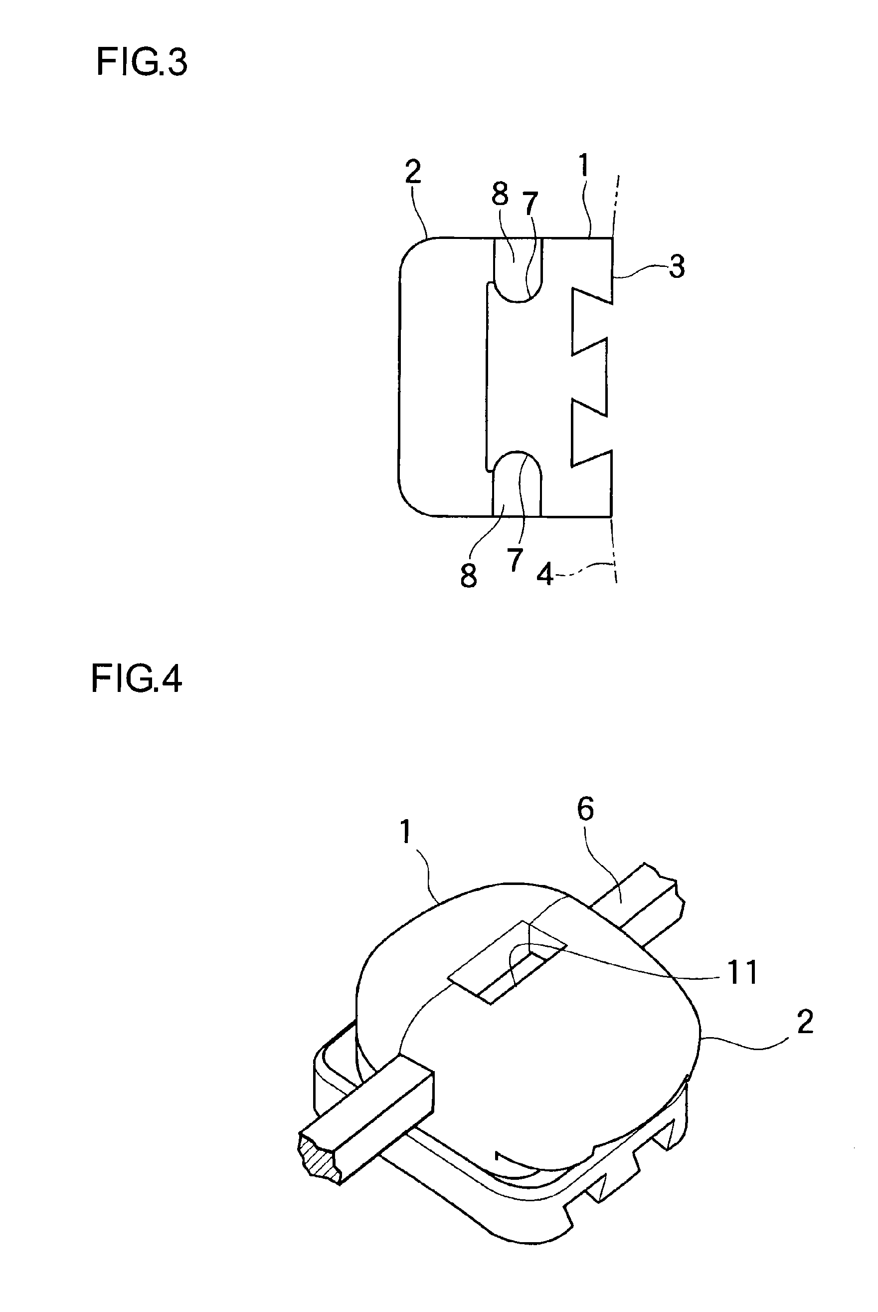
[0094]FIG. 1 is a plan view of an orthodontic bracket according to a first embodiment of the present invention. FIG. 2 is a front view of the orthodontic bracket shown FIG. 1. FIG. 3 is a side view of the orthodontic bracket shown FIG. 1. FIG. 4 is an external view of the orthodontic bracket according to the first embodiment. FIG. 5 is a plan view of an orthodontic bracket showing a state in which a slider portion in the first embodiment is extracted. FIG. 6 is a front view of FIG. 5.

[0095]FIGS. 7 to 11 are drawings showing the configuration of the orthodontic bracket alone in the first embodiment. FIG. 7 is a plan view of the bracket body in the first embodiment. FIG. 8 is a front view of FIG. 7. FIG. 9 is a side view of FIG. 7. FIG. 10 is a cross-sectional view of FIG. 8 taken along line X-X. FIG. 11 is an external view of the bracket body alone in the first embodiment. FIG. 12 is a plan view of a slider portion in the first embodiment. FIG. 13 is a front view of FIG. 12. FIG. 14 ...

second embodiment

[0118]Explanation of a second embodiment will be made in accordance with FIGS. 21 and 22. FIG. 21 is a front view showing a second embodiment, which exemplifies an orthodontic bracket that is aligned with an anterior maxillary tooth. Although the shape of the face 20 for joining to a tooth and its surroundings in this embodiment differs from one in the embodiment mentioned above and the shape of the bracket body also differs, the configuration of the slider portion 2 is completely identical. While the configuration is not shown, it is the same for other teeth as well.

[0119]FIG. 22 shows an example in which elastic action of a wire is increased in the case of a thin archwire 21. While the above-mentioned slider portion 2 is composed to match standard slot dimensions, a gap is formed between the archwire 21 and the through groove 12 of the above-mentioned slider portion 2 in the case where the width dimension of the archwire 21 is small. There are cases in which an intended elastic ef...

third embodiment

[0122]Next, an explanation of a third embodiment will be made in accordance with FIGS. 23 to 29. This embodiment is an example of accommodating orthodontic treatment in the case of prominent crowding of teeth; In cases in which an archwire cannot be inserted into the slot in ordinary manners, unnecessary force ends up being excessively applied to the teeth when the archwire is forcibly inserted into the slot. In order to avoid this in such cases, the archwire of a bracket of a known wire ligating type is weakly ligated with a ligature wire with a portion of the archwire inserted into the slot and left in a suspended state. Further, in the case of a known self-ligating type of bracket in which the slot is covered, the cover portion can be left open by suspending a portion of the archwire from the slot. Moreover, since a ligature wire or rubber band cannot be used in the absence of wings, the configuration mentioned below is employed.

[0123]FIGS. 23 and 24 show an embodiment in which a...


PUM


Abstract

The orthodontic bracket according to the present invention is provided with ligating means having a simple configuration, has additional functions for improving therapeutic effect and improving aesthetic appearance and enables maintenance to be carried out easily. A movable slider portion 2 for pinching an upper portion and a lower portion of an archwire to hold the archwire is provided in order to hold the archwire with respect to a bracket body 1 that has a slot 5 for holding the archwire. This slider portion 2 is inserted into the bracket body 1 to thereby hold the archwire 6. An orthodontic bracket composed of the bracket body 1 and the slider portion 2 has aesthetic properties by having a rounded shape with few surface irregularities. The slider portion 2 can be readily moved with an operating tool 14 and can be easily attached and detached.

Description

TECHNICAL FIELD[0001]The present invention relates to an orthodontic bracket used for orthodontic treatment. More particularly, the present invention relates to an orthodontic bracket that improves aesthetic appearance, facilitates ligation of an archwire and has an additional function of improving therapeutic effect.BACKGROUND OF THE INVENTION[0002]The use of brackets is widely known as orthodontic treatment for malocclusion. Dental arch is corrected by attaching brackets and the like to teeth and applying physical tension, namely a restoring force, such as a pushing force, a pulling-back force or a torsion force, of an archwire attached to these brackets, to the teeth to gradually change the positions of the teeth.[0003]For normal use, a groove is formed in the bracket for causing an archwire to slide or be fixed in the center of the bracket body and the archwire is held in the groove by various ligating means. In the case of emphasizing aesthetic appearance in particular, plastic...

Claims


Application Information

Patent Timeline
Patent Type & Authority Patents(United States)
IPC IPC(8): A61C7/14
CPCA61C7/14A61C7/287
Inventor KANOMI, RYUZOOHKI, TOSHIMITSU
Owner DENTSPLY SANKIN KK
Why Eureka
Try Eureka