Training apparatus for calf roping

a training apparatus and calf roping technology, applied in the field of calf roping training apparatus, can solve the problems of inability to provide adequate live animal practice, inability to develop and improve the skills of calf roping participants, and inability to achieve adequate practice repetitions

Inactive Publication Date: 2012-10-30
REYNOLDS WILLIAM CLARK
View PDF36 Cites 14 Cited by
  • Summary
  • Abstract
  • Description
  • Claims
  • Application Information

AI Technical Summary

Benefits of technology

[0020]The spin joint has a spin shaft, spin sleeve with spin track, and spin ramp of the spin joint. The spin ramp is in a round tubular form affixed to or integrated with the spin shaft which is also a round tube or solid shaft. The spin shaft and the spin ramp are fixed in position, being anchored to the tow member and attached to the short skid, and do not spin with the simulated calf. The spin sleeve is also in a round tubular form and is affixed to the invert receiver. The inside diameter of the spin sleeve is slightly larger than the outside diameter of the spin shaft so that the spin sleeve can rotate freely on the spin shaft as the simulated calf is spun from the forward configuration to the rearward configuration.
[0021]When the simulated calf body is rotated to the rearward configuration and the spin sleeve and the spin track of the spin joint are in a track lowered configuration, the track contact surface is in more or less full contact with the ramp contact surface and the spin joint is now in the spin joint lowered configuration. The raised calf body configuration, which is the configuration of the calf body as the simulated calf is roped by the roper, provides for the simulated legs of the calf to clear the tow member, transverse skid members and the skids as the calf rotates from the forward configuration to the rearward configuration. The calf body is lowered from the raised configuration to the lowered configuration as it spins from the forward configuration to the rearward configuration but maintains clearance for the legs as it spins over the tow member, the skid cross members, and the skids to clear those items before finally being lowered to the lowered configuration. The raised configuration of the simulated calf body is fine for roping of the calf by the roper, but the calf needs to be in the lowered position with the calf body the correct distance above the ground as the roper approaches, blocks, grasps and inverts the calf.
[0023]A structure and leg assembly substantially identical to that used for the hind legs may be used for preferred embodiments of the front legs. The front leg joint assemblies attach the front legs to the body frame in respective front leg anatomical positions. Alternatively, since only one of the front legs is involved in the leg tying task which completes the calf roping event, the left front leg may be omitted or a rigid left front leg may be affixed to the body frame. A pair of hind leg springs and a right front leg spring maintain the simulated calf legs in a neutral position as the calf is being roped, spun, and inverted, and provide the needed simulated resistive force as the right front leg and the two hind legs are pulled together by the roper for the final leg tying task.
[0024]The invert joint has an invert insert and an invert receiver. The invert insert has an insert collar, the horizontal cross-section dimensions of the insert collar being only slightly smaller than the corresponding internal dimensions of the invert receiver thereby providing for the invert insert to remain locked with the invert receiver as the calf body is spun from the forward configuration to the rearward configuration. If, however, the calf is roped incorrectly or the calf is orientated directly away from the force of the rope, and as a result the calf is jerked directly rearward and therefore comes over backwards rather than being spun to the left or the right, the limited depth of the insert collar and the insert gap between the invert insert and the invert receiver will allow the separation of the invert insert and the invert receiver in this scenario and allow the calf body to rotate directly up and backwards thereby allowing a natural result from an incorrect roping effort by the roper or an unfortunate orientation of the calf.
[0025]If the calf is rotated from the forward configuration to the rearward configuration successfully as a result of a proper execution of the roping task by the roper and the roper approaches the calf on foot, grasping the hondo with his left hand and the calf's right hind flank with his right hand and lifts the calf as would be required to lift a live calf off its feet, the invert insert is lifted in the invert receiver above the insert crown, and the insert front tapered zone then allows for the front of the calf to be rotated up somewhat and the insert right tapered zone allows for the invert insert to separate from the invert receiver and for the right side of the calf to rotated up approximately ninety (90) degrees so that the legs of the calf are extended more or less horizontally away from the roper, all for a motion correct inversion of the calf. The lifting and inverting of the simulated calf body can therefore be accomplished in a naturally simulated fashion, allowing the roper to lower the calf to the ground with the legs oriented away from the roper. The tying of the legs can then likewise be accomplished in a naturally simulated fashion, finishing the roping, inversion, and leg tying tasks of the calf roping event.

Problems solved by technology

The principal difficulty that many calf roping participants face in regard to developing and improving their skills is how to get the sufficient practice repetitions.
Unless there are a large number of calves in this weight range available for practice, or animals are used repetitively in an inhumane manner, i.e., excessive numbers of repetitions, adequate live animal practice is beyond the reach of most competitors.
Unfortunately there has not been a suitable apparatus developed to provide for realistic simulation of all of the aspects of the calf roping event.
As the calf runs away from the chute it gets to the end of the lightweight rope which causes a tug on the rope, causing the rope to fall off the calf and tripping the trip lever.

Method used


Image

  • Training apparatus for calf roping
  • Training apparatus for calf roping
  • Training apparatus for calf roping

Examples


Embodiment Construction

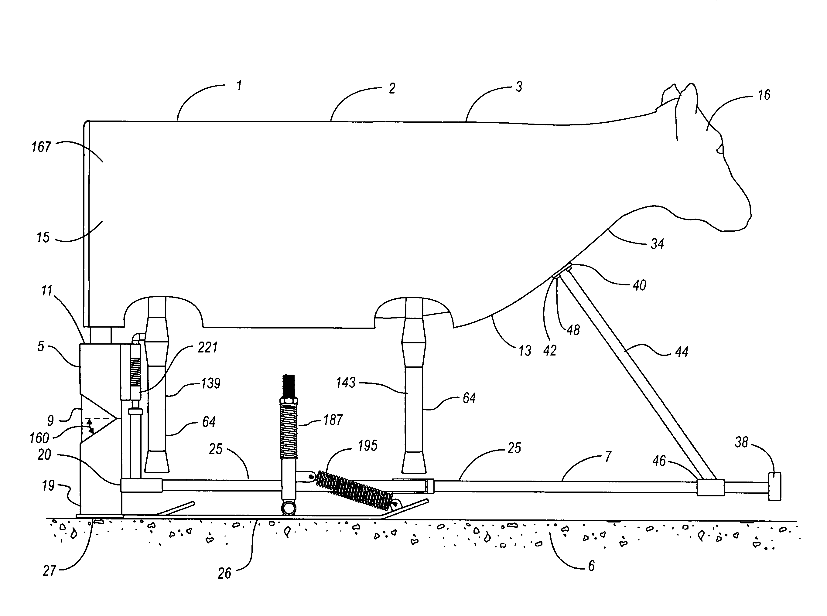
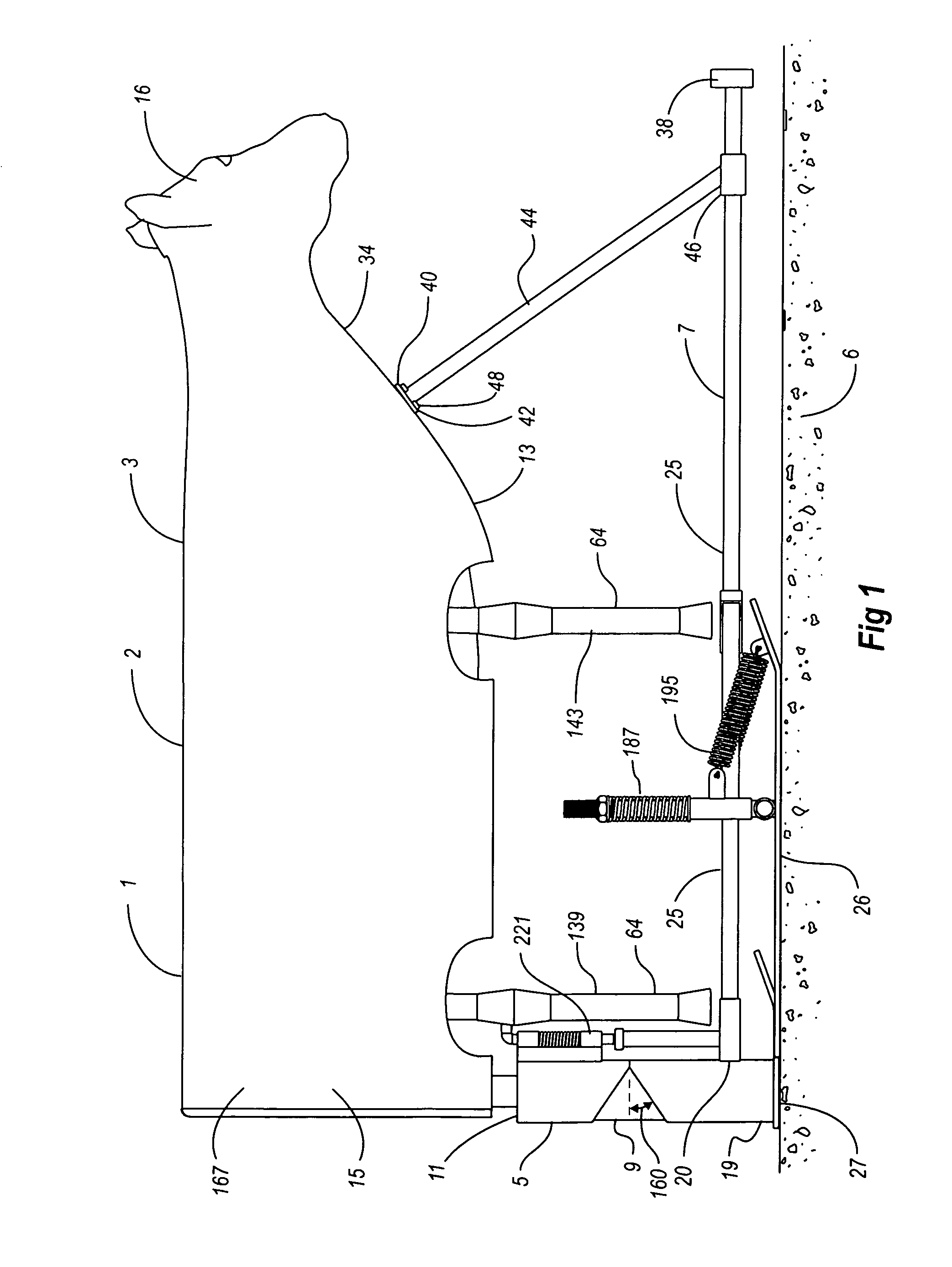
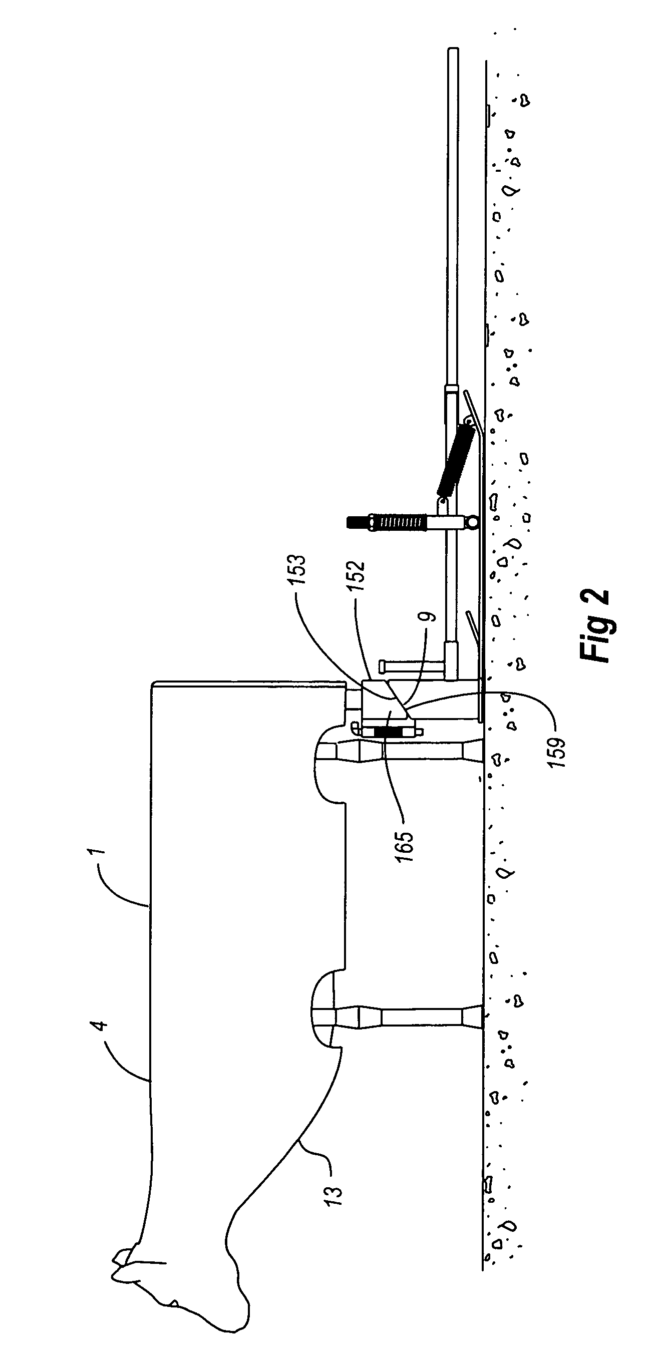
[0050]Referring first to FIG. 1 a preferred embodiment of the calf roping training apparatus 1 of the present invention in a forward configuration 2 is shown. The preferred embodiment shown comprises a simulated calf 3, a support column 5 and a towing structure 7. The support column incorporates two of the key features of the present invention, referred to in this application as the spin joint 9 and the invert joint 11. Referring also to FIG. 8, the calf body 13 of the simulated calf 3 is formed by one or more pieces of simulated skin 15 and a simulated head 16 fixed in anatomical form by a body frame 171. Referring also to FIG. 5 and FIG. 10, the support column 5 is anchored to the tow member end 20 of the tow member 25 of the towing structure 7. The support column base 19 is attached to a short skid 27 which provides for transfer of the weight of the simulated calf 3 to the ground 6. The support column extends upwardly from the short skid. Referring also to FIG. 3, the support col...


PUM


Abstract

A calf roping training apparatus incorporating a simulated calf, a support column and a towing structure. The support column has a spin joint and an invert joint. The calf body of the simulated calf is formed by one or more pieces of simulated skin and a simulated head fixed in anatomical form by a body frame. The support column is anchored to the towing structure. The towing structure has a tow member, a pair of long skids, a short skid, and a towing attachment device. The support column base is attached to the short skid which provides for transfer of the weight of the simulated calf to the ground. The support column top is attached to or integrated with the body frame.

Description

BACKGROUND OF THE INVENTION[0001]Calf roping is a very popular rodeo event which developed from a skill that was needed for cattle ranching in this country and many others. The popularity of calf roping, both for the participants and for the spectators, is probably attributable to a number of factors. Calf roping requires the use of a highly trained horse and requires the roper and the horse to work as a finely coordinated team. Roping skills are also paramount for the roper. Also, while the roper must be agile and reasonably strong to be a serious competitor in this event, the event does allow participants of varying physiques and ages to participate, unlike a number of the other rodeo events which highly favor participants of a particular physique and a younger age.[0002]The principal difficulty that many calf roping participants face in regard to developing and improving their skills is how to get the sufficient practice repetitions. Practice ordinarily includes the use of the ro...

Claims


Application Information

Patent Timeline
Patent Type & Authority Patents(United States)
IPC IPC(8): G09B19/00A01K15/02
CPCG09B9/00G09B19/003
Inventor REYNOLDS, WILLIAM CLARK
Owner REYNOLDS WILLIAM CLARK
Why Eureka
Try Eureka