Floor covering and installation method

a technology for installing methods and floor coverings, applied in the field of floor coverings, can solve the problems of floorboard damage, difficulty in establishing the formfitting connection for the respective other side, and difficulty in installing floorboards, and achieve the effect of simplifying the handling of locking tongues

Active Publication Date: 2012-11-06
SCHULTE GUIDO
View PDF9 Cites 135 Cited by
  • Summary
  • Abstract
  • Description
  • Claims
  • Application Information

AI Technical Summary

Benefits of technology

[0038]If the locking tongue is configured so as to return to the initial groove when the bias force is removed, i.e., when the end of the locking tongue automatically protrudes again from the groove, then this represents an automatic release when the floor covering is pulled up. This is also a significant advantage compared to conventional installation methods, where the locking tongue must be removed by moving the floorboards relative to one another.
[0039]According to another embodiment, the lockin...

Problems solved by technology

The floorboards are sometimes difficult to install.
Once the mechanical locking elements between groove and tongue are interlocked in the longitudinal side or head face, it beco...

Method used


Image

  • Floor covering and installation method
  • Floor covering and installation method
  • Floor covering and installation method

Examples


Embodiment Construction

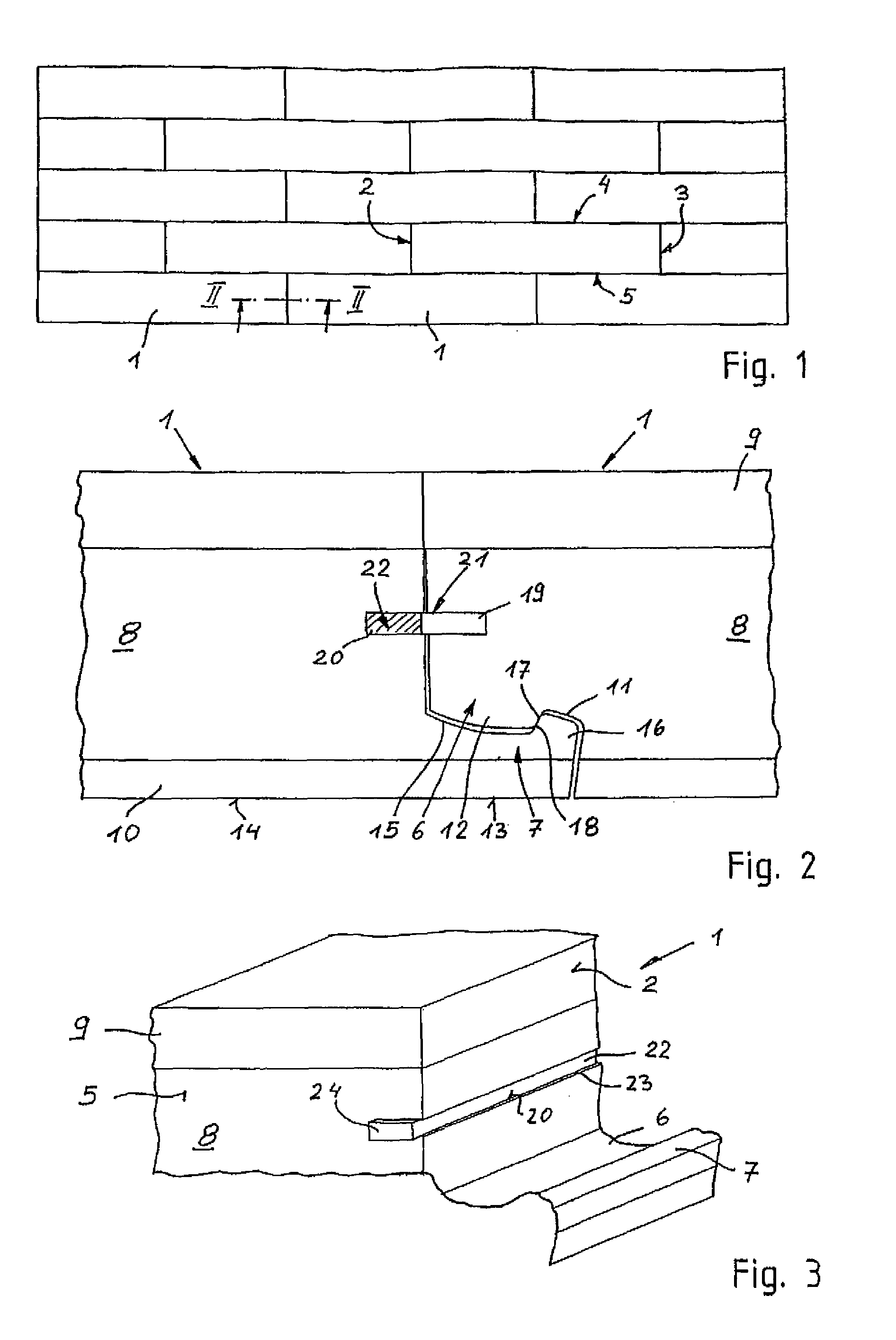
[0054]FIG. 1 shows a floor covering made of a plurality of interconnected rectangular floorboards 1. The floorboards 1 include locking rails disposed on their head faces 2, 3 and on their longitudinal sides 4, 5. In the installation position, the locking rails engage in a floor covering with an adjacent panel.

[0055]Locking rails 6, 7 at the head faces 2, 3 of a floorboard 1 are illustrated in FIG. 2, which shows a vertical cross section through the head-face joint region between two floorboards 1, as viewed down on the joint at the head faces 2, 3. The locking rails on the longitudinal sides of a floorboard 1 (not shown) can be configured different from the locking rails 6, 7.

[0056]The floorboard 1 is made of a support layer 8 of a fiber material, typically a high-compression or medium-compression fiber panel, wherein the support layer 8 has a top cover layer 9 and a bottom resistance member 10. The cover layer 9 can be made of decorative paper with an overlay, which determines the ...


PUM


Abstract

Floor covering comprising a plurality of unit panels (1) laid in a pattern, these panels being provided on their head sides (2, 3) and on their longitudinal sides (4, 5) with locking strips (6, 7) which engage with one another in the assembled position in which unit panels (1) are arranged adjacently within a covering, wherein grooves (19, 20) are provided in the head sides (2, 3) and wherein the grooves (19, 20) of two abutting head sides (2, 3) correspond and form a locking channel (21) intended to accommodate a head tongue (22, 22a-k). The head tongue (22) is preassembled in the groove (20) and projects beyond an end of the groove (20) that faces the longitudinal side (5) of the unit panel (1). At the same time, the head tongue (22) in the preassembled state is embedded completely within the groove (20) and can be displaced at least partially from one groove (20) into the corresponding groove (19) of the adjacent unit panel (1) by sliding the projecting end (24) of the head tongue (22) into the groove (20).

Description

BACKGROUND OF THE INVENTION[0001]The invention relates to a floor covering and to an installation method.[0002]Prefinished parquet, hardwood floors or laminate floors are constructed from several rows of floorboards having a largely rectangular configuration. Conventional floorboards have on one longitudinal side and one head face continuous grooves, and on the corresponding opposite longitudinal side or head face continuous tongues which formfittingly match the grooves. The floorboards are installed by joining grooves and tongues, whereby the floorboards of two adjacent rows are arranged with a mutual offset.[0003]It is known to provide on the grooves and tongues mechanical locking means which lockingly engage in adjacent floorboards of the floor covering. This arrangement is intended to prevent gaps from forming in the installed floor covering due to expansion or contraction processes. Matching locking elements are formed on the groove and tongue of the floorboards as indentations...

Claims


Application Information

Patent Timeline
IPC IPC(8): E04B1/00
CPCE04F15/02E04F15/04E04F2201/0138E04F2201/0153Y10T428/167E04F2201/0523E04F2201/0541E04F2201/0547F16B5/0044E04F2201/0169
Inventor SCHULTE, GUIDO
Owner SCHULTE GUIDO
Why Eureka
Try Eureka