Multistage transmission

a multi-stage transmission and transmission shaft technology, applied in mechanical actuators, mechanical apparatus, gearing, etc., can solve the problems of large shift shock, escape of driving force, difficult to smoothly move the cylindrical body, etc., to reduce the shift shock, increase the reduction ratio

Active Publication Date: 2012-11-06
HONDA MOTOR CO LTD
View PDF23 Cites 10 Cited by
  • Summary
  • Abstract
  • Description
  • Claims
  • Application Information

AI Technical Summary

Benefits of technology

[0037]According to the embodiment of the present invention, in the constant-mesh type multistage transmission, when the shift drive means executes upshift to a one-step-upper speed-change stage reduced in reduction ratio by one stage, the normal rotation odd-numbered stage cam rod and the normal rotation even-numbered stage cam rod alternately operate the normal rotation odd-numbered stage engaging members and the normal rotation even-numbered stage engaging members for shifting. Therefore, in the state where the one engage member is engaged with the gear, the other engaging member comes into engagement with the gear of the one-stage-upper speed-change stage for shifting. At this time, due to the rotation speed difference between the associated gears, the engagement of the one-stage-upper gear with the gear shaft by the other engaging member smoothly releases the engagement of the one-stage-lower gear with the gear shaft by the one engaging member. Thus, the multiple transmission smoothly operates without the necessity of force for the disengagement to eliminate a shift clutch. In addition, the multistage transmission does not cause a loss of the switching time during upshift at all and also does not cause escape of a drive force and reduces a shift shock so as to execute smooth upshift.
[0038]According to the embodiment of the present invention, when the shift drive means executes downshift to a one-step-lower speed-change stage increased in reduction ratio by one stage, the reverse rotation odd-numbered stage cam rod and the reverse rotation even-numbered stage cam rod alternately operate the reverse rotation odd-numbered stage engaging member and the reverse rotation even-numbered stage engaging member for shifting. Therefore, in the state where the one engaging member is engaged with the gear, the other engaging member comes into engagement with the gear of the one-stage-lower speed-change stage for shifting. At this time, due to the rotation speed difference between the associated gears, the engagement of the one-stage-lower gear with the gear shaft by the other engaging member smoothly releases the engagement of the one-stage-upper gear with the gear shaft by the one engaging member. Thus, the multistage transmission smoothly operates without the necessity of force for the disengagement to eliminate a shift clutch. In addition, the multistage transmission does not cause a loss of the switching time at all during downshift and also does not cause escape of a drive force and reduces a shift shock so as to execute smooth downshift.
[0039]According to the embodiment of the present invention, the odd-numbered stage cam grooves of the normal rotation odd-numbered stage cam rod and the even-numbered stage cam grooves of the reverse rotation even-stage cam rod are formed on a single cam rod as a first common cam rod, and the even-numbered stage cam grooves of the normal rotation even-numbered stage cam rod and the odd-numbered stage cam grooves of the reverse rotation odd-stage cam rod are formed on a single cam rod as a second common cam rod. Thus, the kinds of the cam rods can be made two.
[0040]According to the embodiment of the present invention, the first lost motion mechanism allows the control rod to simultaneously move the normal rotation odd-numbered stage cam rod and the reverse rotation even-numbered stage cam rod, and the second lost motion mechanism allows the control rod to simultaneously move the normal rotation even-numbered stage cam rod and the reverse rotation odd-numbered stage cam rod. Thus, the two lost motion mechanisms can move the four kinds of the cam rods simultaneously with the single control rod.
[0041]According to the embodiment of the present invention, since the cam member is an axially elongated prismatic bar member rectangular in cross-section and is formed with a cam surface on one lateral surface thereof. Thus, the cam member can easily be manufactured from the prismatic bar member that does not have a special shape in cross-section but has a simple rectangular outer shape.
[0042]In addition, the gear shaft is formed with, on the hollow inner circumferential surface, the cam guide groove extending toward an axial direction to receive the cam member rectangular in cross-section slidably fitted into the hollow inner circumferential surface for guiding it. Therefore, the cam guide groove serving as a locking member for the cam member relative to the gear shaft is simply rectangular U-shaped in cross-section so that it can simply be formed.

Problems solved by technology

Therefore, a significantly large force is needed to release this engagement so that it is not easy to smoothly move the cylindrical body.
In addition, during shifting, when the engagement of the rollers with the driven gear is released, escape of a driving force occurs and a large shift shock occurs at the time of engaging with the adjacent driven gear.
Thus, smooth shifting is difficult.
Therefore, they cannot be manufactured with ease.
In addition, it is not easy to form the projecting ridges for locking on the hollow inner circumferential surface of the gear shaft.
However, since the lost motion mechanisms are arranged at both the ends of the cam rods, the gear shaft is increased in length to increase the axial width of the transmission, which leads to the enlarged transmission.

Method used


Image

  • Multistage transmission
  • Multistage transmission
  • Multistage transmission

Examples


Embodiment Construction

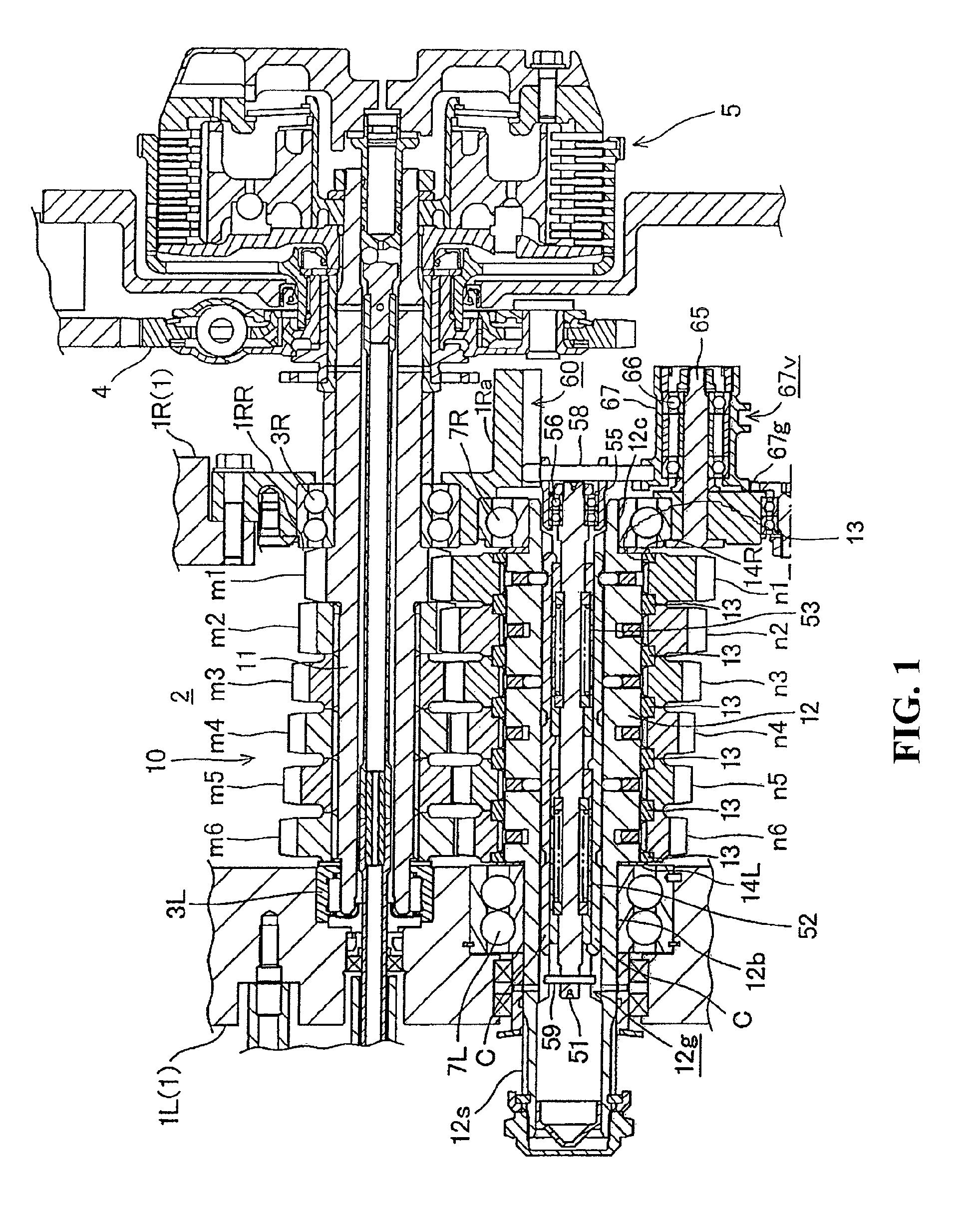
[0070]An embodiment of the present invention will hereinafter be described with reference to FIGS. 1 to 20.

[0071]A multistage transmission 10 according to the present embodiment is configured to be built into an internal combustion engine mounted on a motorcycle.

[0072]FIG. 1 is a cross-sectional view of the multistate transmission 10. As illustrated in FIG. 1, the multistage transmission 10 is provided in an engine case 1 shared by the internal combustion engine.

[0073]This engine case 1 is formed by combining a left engine case 1L and a right engine case 1R which are right-left split from each other. The engine case 1 forms a speed-change chamber 2. A main gear shaft 11 and a counter gear shaft 12 are rotatably supported by the speed-change chamber 2 so as to extend parallel to each other in a right-left direction.

[0074]The main gear shaft 11 is rotatably supported by a sidewall of the left engine case 1L and a sidewall 1RR of the right engine case 1R via bearings 3L and 3R, respect...


PUM


Abstract

A multistage transmission is provided that smoothly operates with a small force without the necessity of a shift clutch, that does not cause a loss of switching time during shifting, and that does not cause escape of a driving force as well as provides a small shift shock. When shift drive means executes upshift to a one-step-upper speed-change stage reduced in reduction ratio by one stage, normal rotation odd-numbered stage cam rods Cao and normal rotation even-numbered stage cam rods Cae alternately operate normal rotation odd-numbered stage engaging members Rao and the normal rotation odd-numbered stage engaging members Rae for shifting.

Description

CROSS-REFERENCE TO RELATED APPLICATION[0001]The present application claims priority under 35 U.S.C. §119 to Japanese Patent Application Nos. 2008-246755, 2008-246754, and 2008-246752, each filed Sep. 25, 2008, the entire contents of which are hereby incorporated by reference.BACKGROUND OF THE INVENTION[0002]1. Field of the Invention[0003]The present invention relates to a multistage transmission in which a plurality of drive gears and driven gears are rotatably supported by respective parallel gear shafts in a constant-mesh state for each speed-change stage.[0004]2. Description of Background Art[0005]A conventional constant-mesh type multistage transmission is such that one of drive gears and driven gears is secured to a gear shaft, the other is rotatably supported by a gear shaft, and a gear engaged with a rotating shaft is switched from the rotatable gears by engaging means for executing shifting.[0006]Engaging means are proposed each of which generally brings a driven gear into e...

Claims


Application Information

Patent Timeline
Patent Type & Authority Patents(United States)
IPC IPC(8): F16H59/00F16H61/00F16H63/00
CPCF16H3/083F16H63/30Y10T74/19279F16H2063/3096F16H2063/3093
Inventor MATSUMOTO, SHINYA
Owner HONDA MOTOR CO LTD
Why Eureka
Try Eureka