Fastener feeder delay for fastener driving tool

a technology of fastener and feeder, which is applied in the field of fastener driving tools, can solve the problems of less reliable mechanism of '264 patent, unsatisfactory nail drive, and less control of nail or collation drive, so as to reduce frictional load, reduce nail or collation malfunction, and improve piston return speed and reliability

Active Publication Date: 2012-11-06
ILLINOIS TOOL WORKS INC
View PDF13 Cites 23 Cited by
  • Summary
  • Abstract
  • Description
  • Claims
  • Application Information

AI Technical Summary

Benefits of technology

[0010]Advantages of the present tool include reduced nail or collation malfunction due to interference with the driver blade during piston return, improved piston return speed and reliability due to reduced frictional load on the drive piston assembly, and increased operational life for the drive piston and the retention device due to low wear. Also, the retention device is lightweight and operates with increased energy efficiency compared to conventional fastener feeder mechanisms. The present device is relatively uncomplicated with few parts to produce, install and maintain, and it is substantially enclosed, resulting in a dirt and debris-tolerant assembly, as opposed to prior art designs, which use small gas passages that are prone to dirt problems and complex mechanisms that can be damaged, require lubricant, are susceptible to corrosion, and can be affected by debris. In the present tool, the control module provides electronically controlled automatic operation of the retention device, and end-user input variability is avoided. Lastly, by providing a relatively simple mechanism which is operable independently of the normal tool functions, the tool actuation force required to be applied by the user prior to driving a fastener is maintained as in conventional tools and is not increased.
[0011]In addition, the gas conduit is connected to the cylinder to obtain sufficient pneumatic force for actuating the magazine feed cylinder, while effectively delaying the actuation of the feeder mechanism feed piston until the driver blade has sufficiently impacted the fastener. It is preferred that the feed piston be delayed until the collations holding the fasteners together are broken. An advantage of this delay is that fastener misalignment is prevented, which reduces fastener jams in the nose and also results in more effective fastener driving. This delay is obtained by moving the port that feeds combustion gas to the feed piston a specified distance below the piston pre-firing position such that the gas is delivered to the feed piston only after the driver blade has impacted the fastener. In other words, the distance the port is displaced below the pre-firing position is determined by the delay in actuating the feed piston, based on driver blade position.

Problems solved by technology

Optimally, the drive piston shears the nail from the collation media before the feed piston begins retraction, otherwise the nail will be driven with less control and an unsatisfactory nail drive can result.
However, the mechanism of the '264 patent proved to be less reliable in that insufficient pneumatic power was supplied to the feed piston.
A drawback of this arrangement is that the feed piston is actuated prematurely, causing misaligned fasteners in the tool nose as well as improperly driven fasteners.
This results in the nail being biased against the driver blade during the return cycle.
The resulting friction prolongs the return of the driver blade, or even worse, prevents the driver blade from returning to the pre-firing position.
This problem can be exacerbated by the amount of dirt, debris or collation media in the nose area of the tool.
The present device is relatively uncomplicated with few parts to produce, install and maintain, and it is substantially enclosed, resulting in a dirt and debris-tolerant assembly, as opposed to prior art designs, which use small gas passages that are prone to dirt problems and complex mechanisms that can be damaged, require lubricant, are susceptible to corrosion, and can be affected by debris.

Method used


Image

  • Fastener feeder delay for fastener driving tool
  • Fastener feeder delay for fastener driving tool
  • Fastener feeder delay for fastener driving tool

Examples


Embodiment Construction

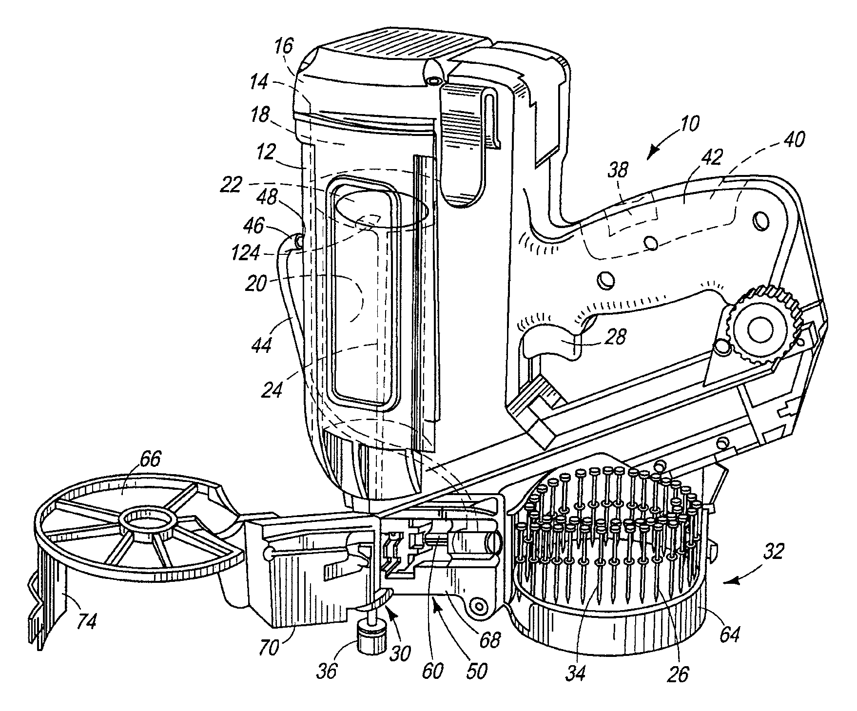
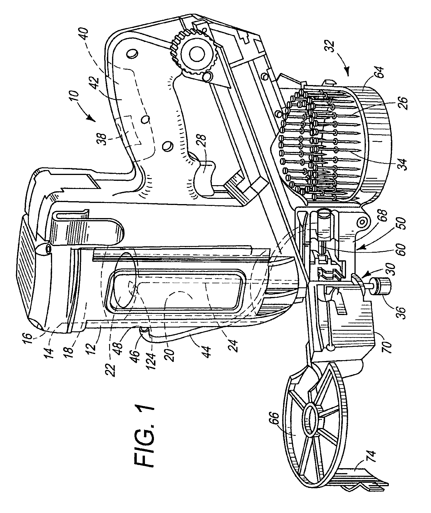
[0028]Referring now to FIGS. 1-4, a fastener driving tool of the type suitable with the present feeder mechanism is generally designated 10 and is depicted as a combustion-powered tool. The general principles of operation of such tools are known in the art and are described in U.S. Pat. Nos. 5,197,646; 4,522,162; 4,483,473; 4,483,474 and 4,403,722, all of which are incorporated by reference. However, it is contemplated that the present feeder mechanism is applicable to fastener driver tools powered by other power sources that employ a reciprocating driver blade for driving fasteners into a workpiece. Also while it should be understood that the tool 10 is operable in a variety of orientations, directional terms such as “upper” and “lower” refer to the tool in the orientation depicted in FIG. 1.

[0029]Referring to FIGS. 1-4 and 11, a housing 12 of the tool 10 encloses a self-contained internal power source 14 (FIG. 11) within a housing main chamber 16. As in conventional combustion too...


PUM


Abstract

A fastener driving tool includes a power source including a cylinder, a piston with a driver blade reciprocating in the cylinder, a tool nose associated with the power source for receiving the driver blade for driving fasteners fed into the nose, and a magazine housing a supply of the fasteners. A magazine feeder mechanism is associated with the magazine for sequentially feeding fasteners into the nose, and the feeder mechanism includes a reciprocating feed piston. A conduit is connected between a port in the cylinder and the feed mechanism for diverting combusted gas for activating the feed piston. The port is disposed in the cylinder a specified distance below a piston prefiring position, and the distance is reflective of a delay of feeding the gas to the feed piston at least until engagement between an end of the driver blade and a head of a fastener in the tool nose.

Description

RELATED APPLICATION[0001]This application is a Continuation-In-Part of U.S. patent application Ser. No. 11 / 820,942 filed Jun. 21, 2007.BACKGROUND OF THE INVENTION[0002]The present invention relates generally to fastener driving tools employing magazines feeding fasteners to a nosepiece for receiving a driving force; and more specifically to such tools employing a fastener feeder mechanism powered with gas pressure generated during the fastener driving process.[0003]Fastener driving tools, referred to here as tools or nailers, are known in the art and are powered by combustion, compressed gas (pneumatic), powder, and electricity. Portable fastener driving tools that drive collated fasteners disposed in a coil magazine are commercially available on the market and are manufactured by ITW Buildex, Itasca, Ill. The core operating principle of the tool and the respective fastener feeding mechanism is defined in ITW U.S. Pat. Nos. 5,558,264 and 7,040,521, both of which are incorporated by ...

Claims


Application Information

Patent Timeline
Patent Type & Authority Patents(United States)
IPC IPC(8): B25C1/08
CPCB25C1/003B25C5/1627B25C1/00B25C1/08B25C5/00B25C5/16
Inventor PORTH, CHRIS H.MOELLER, LARRY M.
Owner ILLINOIS TOOL WORKS INC
Why Eureka
Try Eureka