
Image forming apparatus, misregistration correction control method and computer-readable information recording medium

a technology computer-readable information, applied in the field of image forming apparatus, can solve the problems of user disadvantage, increase in toner consumption, and possible misregistration, and achieve the effect of reducing toner consumption or down tim

Inactive Publication Date: 2012-11-06
RICOH KK
View PDF14 Cites 2 Cited by
  • Summary
  • Abstract
  • Description
  • Claims
  • Application Information

AI Technical Summary

Benefits of technology

The present invention provides an image forming apparatus, method, and computer-readable information recording medium that can determine when misregistration correction is necessary and carry out correction only when necessary, reducing toner consumption and down time. The apparatus includes a pattern forming part to form a pattern image of misregistration correction patterns, a misregistration amount calculating part to calculate the misregistration amount based on the pattern image, a correction performing determination part to determine whether to carry out misregistration correction based on the misregistration amount, and a correcting part to carry out misregistration correction based on the correction performing determination. This invention helps to improve the usability of the image forming apparatus and form stable color images.

Problems solved by technology

However, in the image forming apparatus in the related art, after a certain time has elapsed from a time of misregistration correction being carried out, misregistration may occur again for various reasons.
Therefore, in some cases, misregistration correction may be carried out frequently, and thereby, toner consumption may increase, which causes a disadvantage for a user.
Further, when a printing request is given during misregistration correction being carried out, an extra time is required until the required printing is finished.
When misregistration correction is carried out frequently, a time required for carrying out the misregistration correction may constitute a down time, and may adversely affect the usability of the image forming apparatus.
Further, such a down time may occur also when power supply is started in the image forming apparatus, and thereby, a time delay may be required before the required printing can be started.
However, in these image forming apparatuses in the related art, the above-mentioned problems may not be completely solved.

Method used


Image

  • Image forming apparatus, misregistration correction control method and computer-readable information recording medium
  • Image forming apparatus, misregistration correction control method and computer-readable information recording medium
  • Image forming apparatus, misregistration correction control method and computer-readable information recording medium

Examples


first embodiment

Summary of First Embodiment

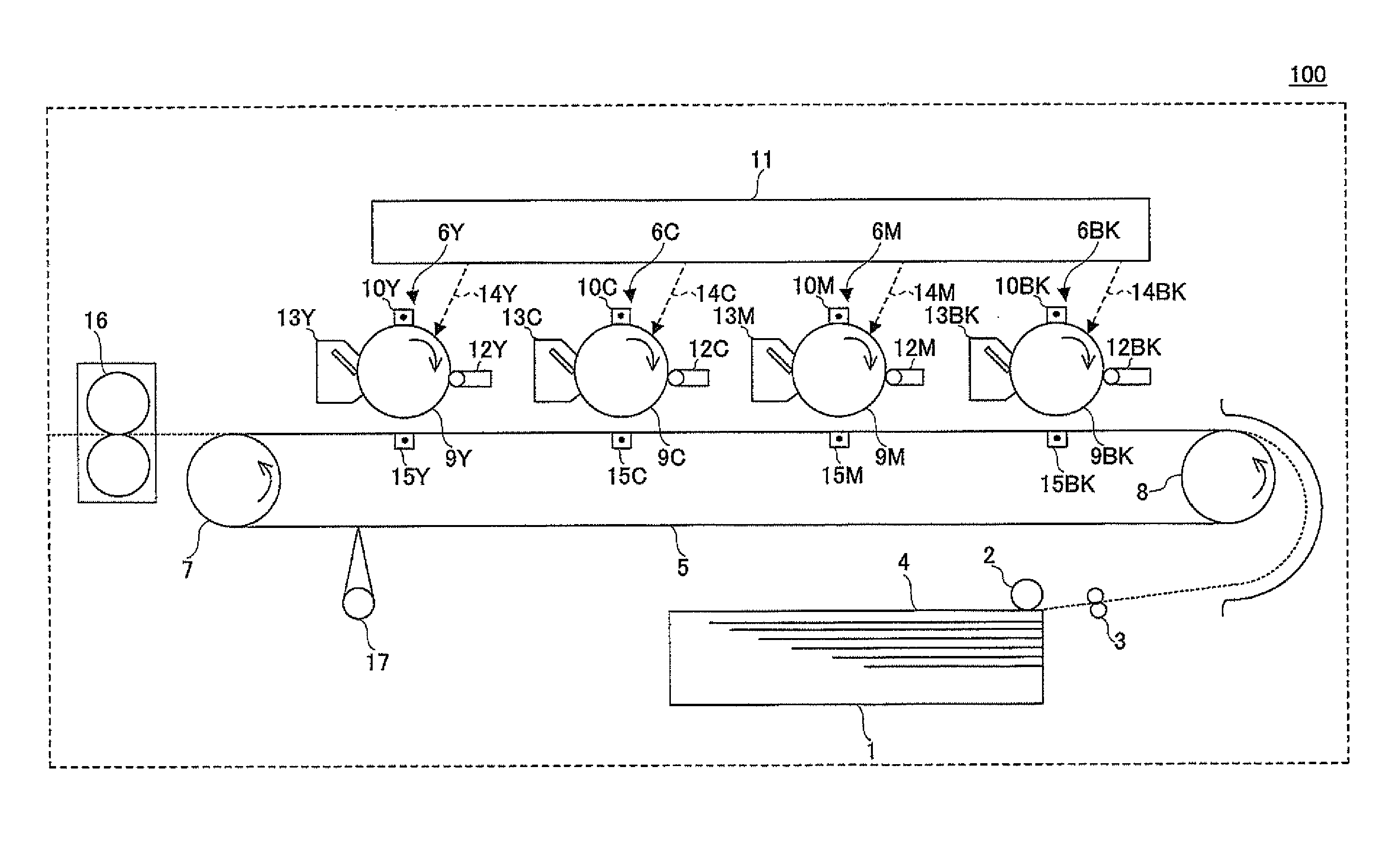
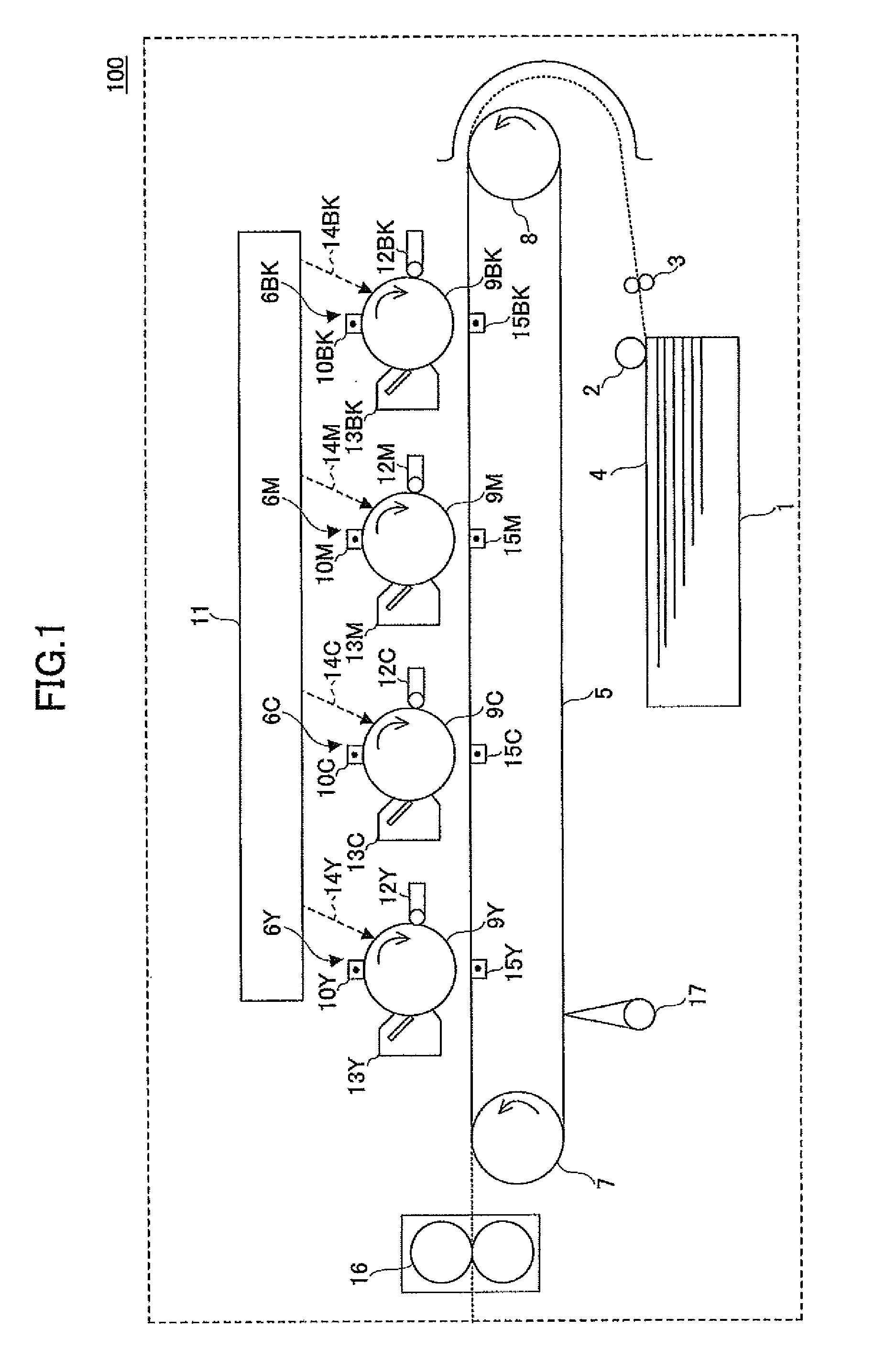
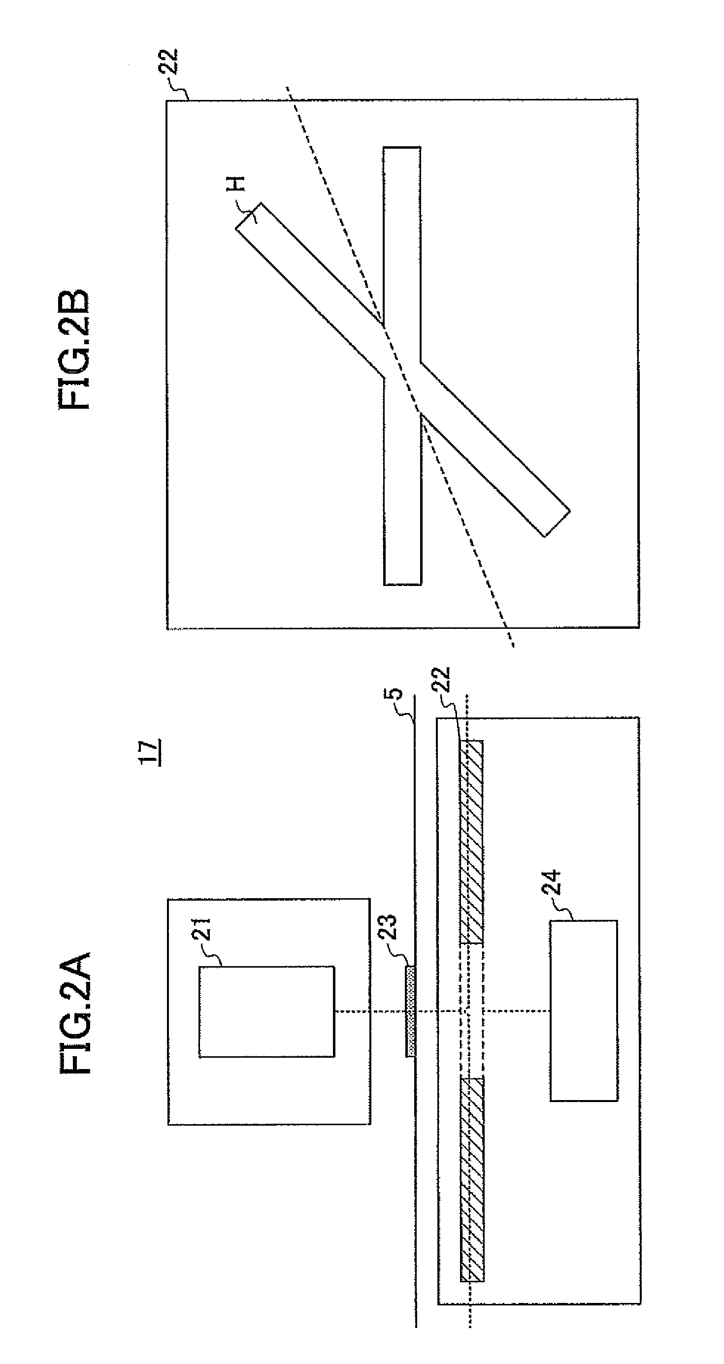
[0189]Thus, according to the first embodiment, the image forming apparatus 100 forms toner mark patterns 23a, 23b and 23c (or 23a and 23c) of the performing determination patterns Pa on the conveyance belt 5 when entering a predetermined operating condition, and the image detecting parts 17a, 17b and 17c (or 17a and 17c) detect the toner marks M. Next, the image forming apparatus 100 calculates misregistration amounts based on pattern positions which have been calculated from the detection results, and determines whether to carry out misregistration correction, based on the calculated misregistration amounts.

[0190]Then, when determining to carry out misregistration correction, the image forming apparatus 100 forms toner mark patterns 23a, 23b and 23c of the correction patterns Pb on the conveyance belt 5, and the image detecting parts 17a, 17b and 17c detect the toner marks M. Next, the image forming apparatus 100 calculates misregistration amounts based o...

second embodiment

Summary of Second Embodiment

[0216]Thus, according to the second embodiment, when entering the predetermined operating condition, the image forming apparatus 100 forms toner mark patterns 23a, 23b and 23c of the performing determination patterns Pa on the conveyance belt 5, and, by means of the image detecting parts 17a, 17b and 17c, detects toner marks M thereof. Next, the image forming apparatus 100 calculates misregistration amounts based on pattern positions calculated from the detection results, and determines, for each color, whether to carry out misregistration correction, based on the calculated misregistration amounts.

[0217]When determining, in the above-mentioned determination, to carry out misregistration correction for a color, the image forming apparatus 100 forms toner mark patterns 23a, 23b and 23c of the correction patterns Pb including only the color for which misregistration correction is to be carried out, and, by means of the image detecting parts 17a, 17b and 17c...


PUM


Abstract

A pattern image of either a registration correction pattern including a plurality of position detecting marks or a misregistration correction performing determination pattern having a plurality of position detecting marks, the number of which marks is smaller than that of the registration correction pattern image is formed. A misregistration amount is calculated based on an image formed position detected with the use of the pattern image. It is determined whether the registration correction is to be carried out, based on the misregistration amount with the use of an image formed position of the correction performing determination pattern. When it is determined to carry out the misregistration correction, the misregistration correction is carried out based on the misregistration amount with the use of image formed positions of the misregistration correction pattern.

Description

BACKGROUND OF THE INVENTION[0001]1. Field of the Invention[0002]The present invention relates to an image forming apparatus which provides an image which is visualized as a result of a plurality of colors being overlaid together, in an electrophotographic printer or such. In particular, the present invention relates to an art of forming misregistration correction patterns, and detecting the thus-formed misregistration correction patterns, to carry out misregistration correction.[0003]2. Description of the Related Art[0004]In a tandem-type image forming apparatus, toner images of respective colors (for example, respective expression colors such as black (BK), cyan (C), magenta (M) and yellow (Y)) are formed by different image forming parts. The toner images are then overlaid together and a color image is formed.[0005]In such an image forming apparatus, a stable color image may not be obtained (i.e., so-called color shifts may occur) when positions (i.e., image formed positions) of to...

Claims


Application Information

Patent Timeline
Patent Type & Authority Patents(United States)
IPC IPC(8): G06F15/00G06K15/00G06K1/00G06K15/22
CPCG03G15/0131G03G15/50G03G2215/00059G03G2215/00063G03G2215/0161G03G15/0194G03G15/5058
Inventor IKEDA, HIROAKI
Owner RICOH KK
Learn More