
System and method for transmission interference cancellation in full duplex transceiver

a transmission interference and full duplex technology, applied in transmission, transmission monitoring, electrical equipment, etc., can solve problems such as imperfect duplexer performance and interference with transmission

Active Publication Date: 2012-11-06
TEXAS INSTR INC
View PDF18 Cites 76 Cited by
  • Summary
  • Abstract
  • Description
  • Claims
  • Application Information

AI Technical Summary

Benefits of technology

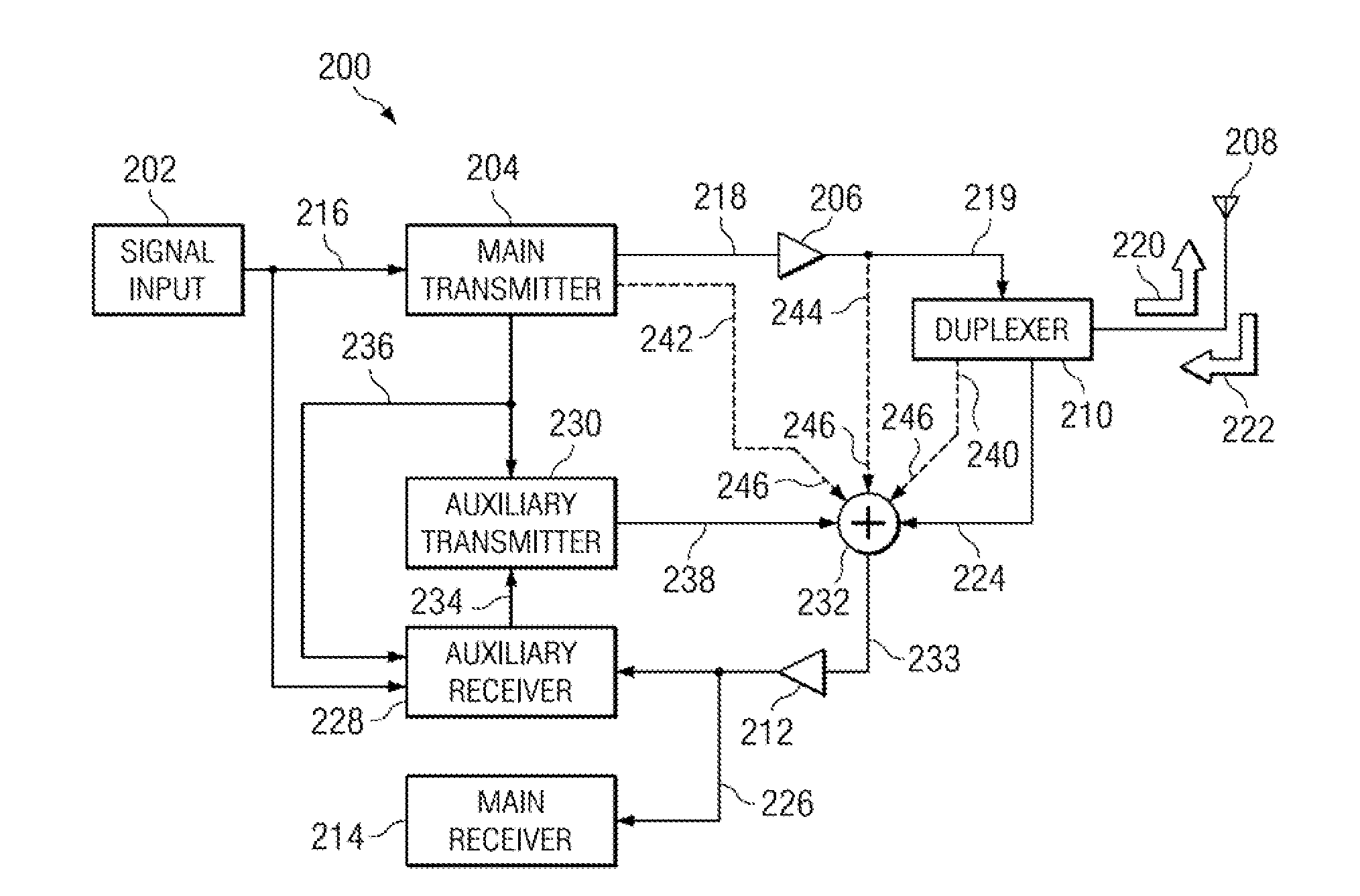
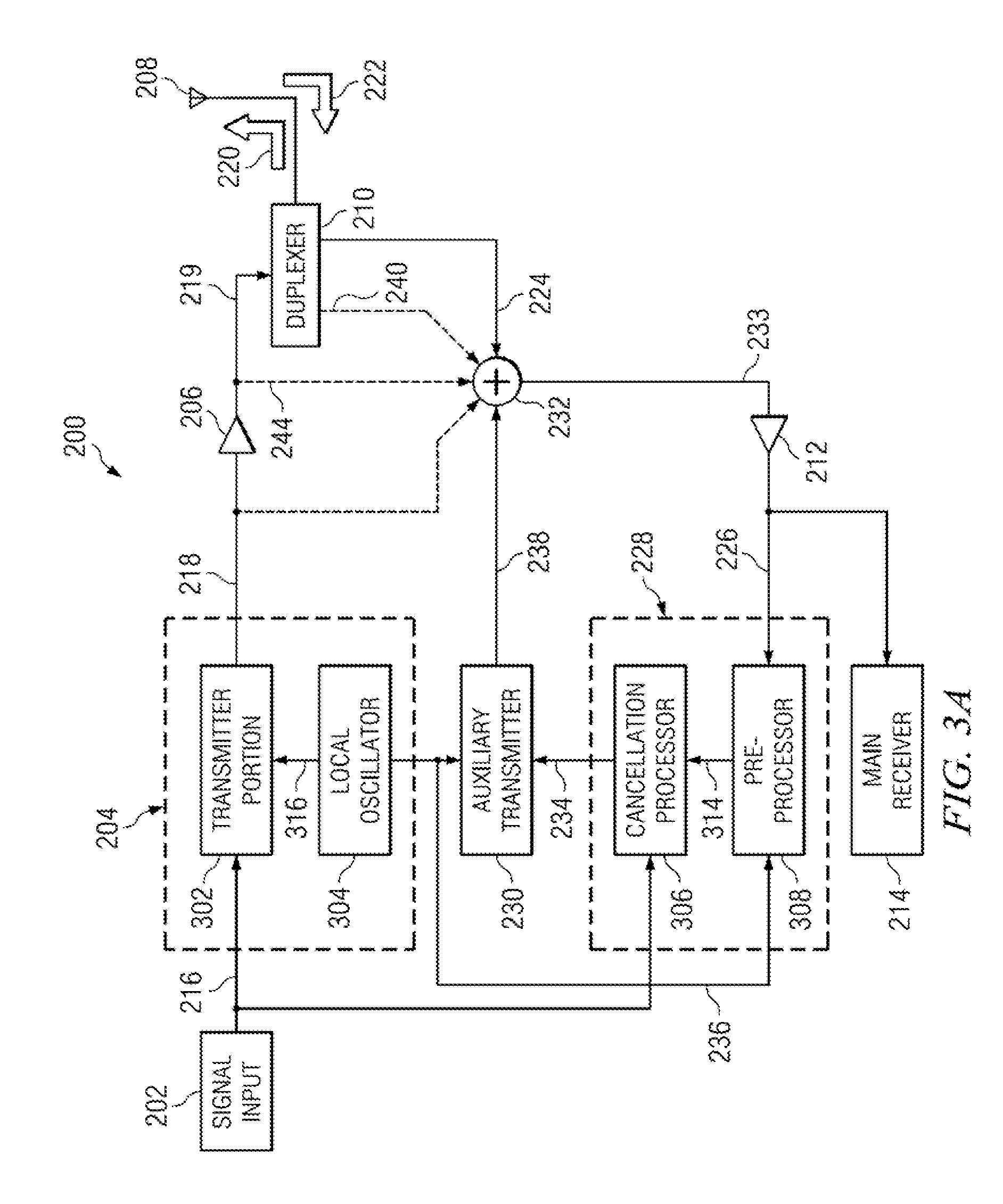
The present invention is about canceling out transmission signal leakage from a received signal in a full duplex transceiver using cancellation circuitry. The cancellation circuitry includes an auxiliary receiver and an auxiliary transmitter. The auxiliary receiver converts the received signal from the analog domain to the digital domain and detects the leakage. The auxiliary transmitter then generates a cancellation signal based on the leakage detection. This cancellation signal is combined with the received signal and sent back to the main receiver. This feedback system helps to cancel out various types of transmission signal leakage from the received signal. The invention also includes a device with a duplexer, combiner, and first and second receivers that can generate a received signal with reduced interference. The technical effects of the invention are improved signal quality and reduced interference in full duplex transceivers.

Problems solved by technology

Any such full duplex transceiver has an inherent problem with self-interference: transmission interferes with reception in a process called transmission leakage even though there should be no overlap in the bands.
Leakage results not only from imperfect duplexer performance in isolating the transmit signal from the reception signal, but also from parasitic coupling paths between multiple elements of the transmission circuitry and the reception circuitry which permit leakage of the transmission signal into the reception signal.
Contemporary market pressures push for smaller and smaller transceiver circuits, thus compounding the problem as transmission circuitry is pressed ever closer to reception circuitry.

Method used


Image

  • System and method for transmission interference cancellation in full duplex transceiver
  • System and method for transmission interference cancellation in full duplex transceiver
  • System and method for transmission interference cancellation in full duplex transceiver

Examples


Embodiment Construction

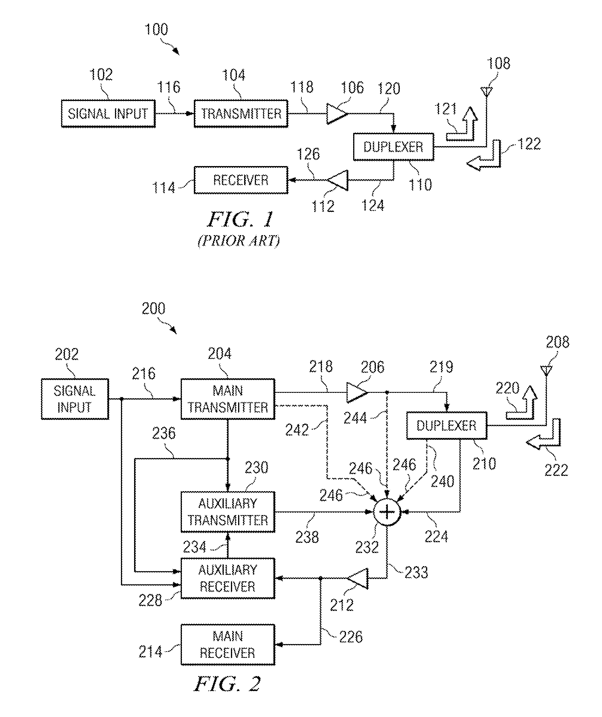
[0024]A full duplex transceiver in accordance with an exemplary embodiment of the invention will now be described with reference to FIG. 2. Transceiver 200 includes signal input 202, main transmitter 204, power amplifier (PA) 206, antenna 208, duplexer 210, low-noise amplifier (LNA) 212, main receiver 214, auxiliary receiver 228, auxiliary transmitter 239 and adder 232.

[0025]In this embodiment, signal input 202, main transmitter 204, power amplifier (PA) 206, antenna 208, duplexer 210, low-noise amplifier (LNA) 212, main receiver 214, auxiliary receiver 228, auxiliary transmitter 230 and adder 232 are distinct elements. However, in other embodiments, at least one of signal input 202, main transmitter 204, power amplifier (PA) 206, antenna 208, duplexer 210, low-noise amplifier (LNA) 212, main receiver 214, auxiliary receiver 228, auxiliary transmitter 230 and adder 232 may be included as a single element of transceiver 200.

[0026]The data to be transmitted 216 from signal input 202 a...


PUM


Abstract

A full duplex transceiver has cancellation circuitry that includes an auxiliary receiver and an auxiliary transmitter. More specifically, an analog received signal that includes transmission signal leakage is provided to a low noise amplifier (LNA), which then provides its output to a main receiver and the auxiliary receiver. The auxiliary receiver includes a portion operable to convert the received signal from the analog domain to the digital domain. The auxiliary receiver additionally includes a cancellation processor that determines the transmission signal leakage and generates a signal based on the determined leakage. This signal generated by the auxiliary receiver is provided to the auxiliary transmitter, which converts the digital signal back to the analog domain and generates a cancellation signal. The analog cancellation signal is fed back and added to the received signal at the input of the LNA. As a result of the feedback system including an auxiliary receiver and an auxiliary transmitter, transmission signal leakage of many types may be canceled from a received signal.

Description

BACKGROUND[0001]Wireless devices such as cellular telephones and Wi-Fi networking devices require the capability to transmit and receive wireless signals simultaneously. This is accomplished with a full duplex transceiver. FIG. 1 illustrates a conventional full duplex transceiver 100, which includes a signal input portion 102, a transmitter 104, an amplifier 106, an antenna 108, a duplexer 110, an amplifier 112 and a receiver 114.[0002]The data to be transmitted 116 are passed from signal input 102 to transmitter 104. Output 118 from transmitter 104 is amplified by amplifier 106. Output 120 from amplifier 106 is supplied to duplexer 110, which generates transmit signal 121 for transmission out of antenna 108.[0003]The transmission frequency of the transceiver is typically lower than the receiving frequency. Ideally, there is no overlap in the transmission frequency band and the receiving frequency band. In the event that antenna 108 receives a reception signal 122 while transmitting...

Claims


Application Information

Patent Timeline
Patent Type & Authority Patents(United States)
IPC IPC(8): H04B17/00
CPCH04B1/525
Inventor MUHAMMAD, KHURRAMELAHI, IMTINAN
Owner TEXAS INSTR INC
Learn More