
Using dynamic call graphs for creating state machines

a dynamic call graph and state machine technology, applied in the direction of source code creation, program control, instruments, etc., can solve the problems of complex design, challenging the extending the life of software, and increasing the complexity of software developmen

Inactive Publication Date: 2012-11-13
IBM CORP
View PDF10 Cites 6 Cited by
  • Summary
  • Abstract
  • Description
  • Claims
  • Application Information

AI Technical Summary

Benefits of technology

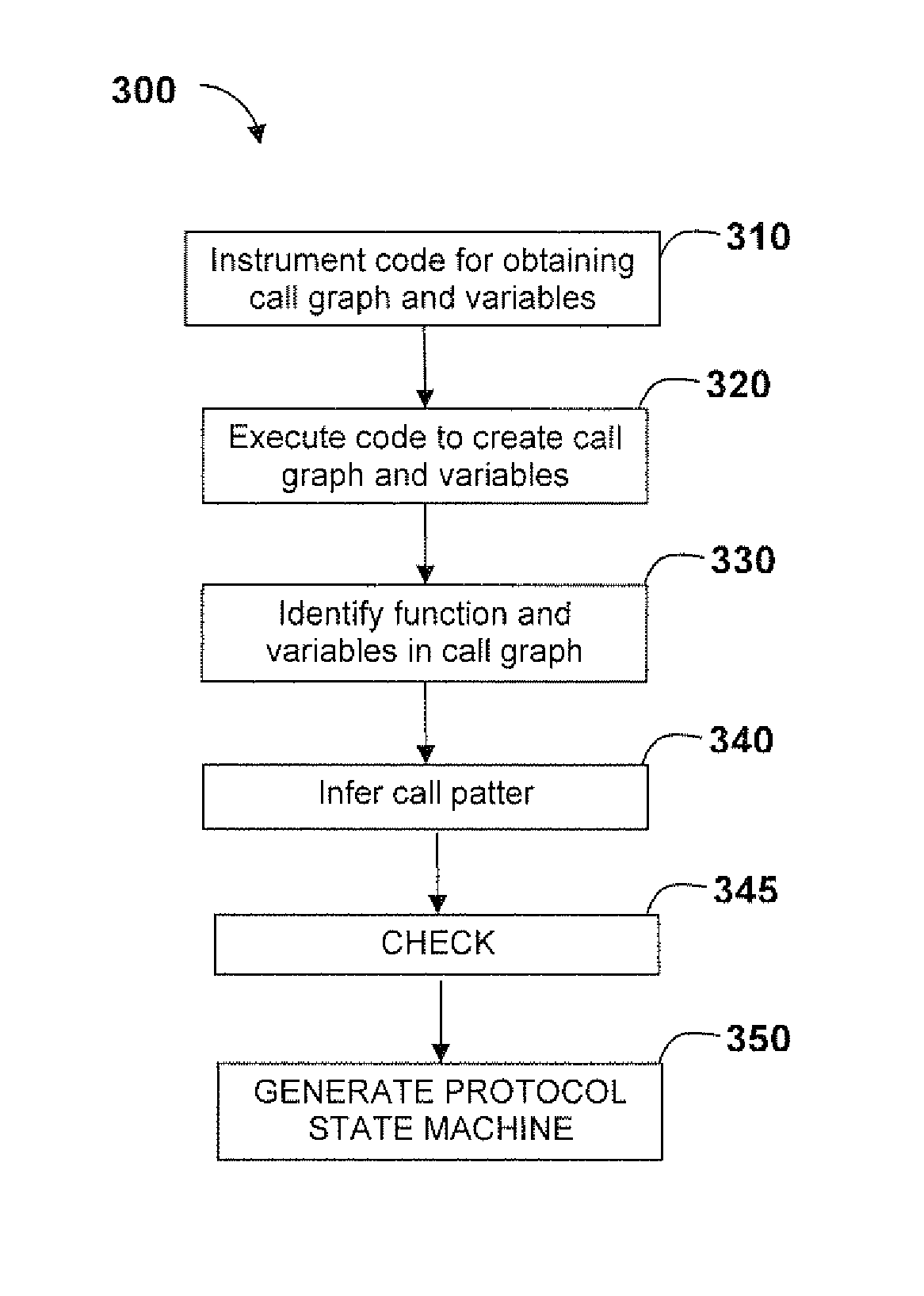
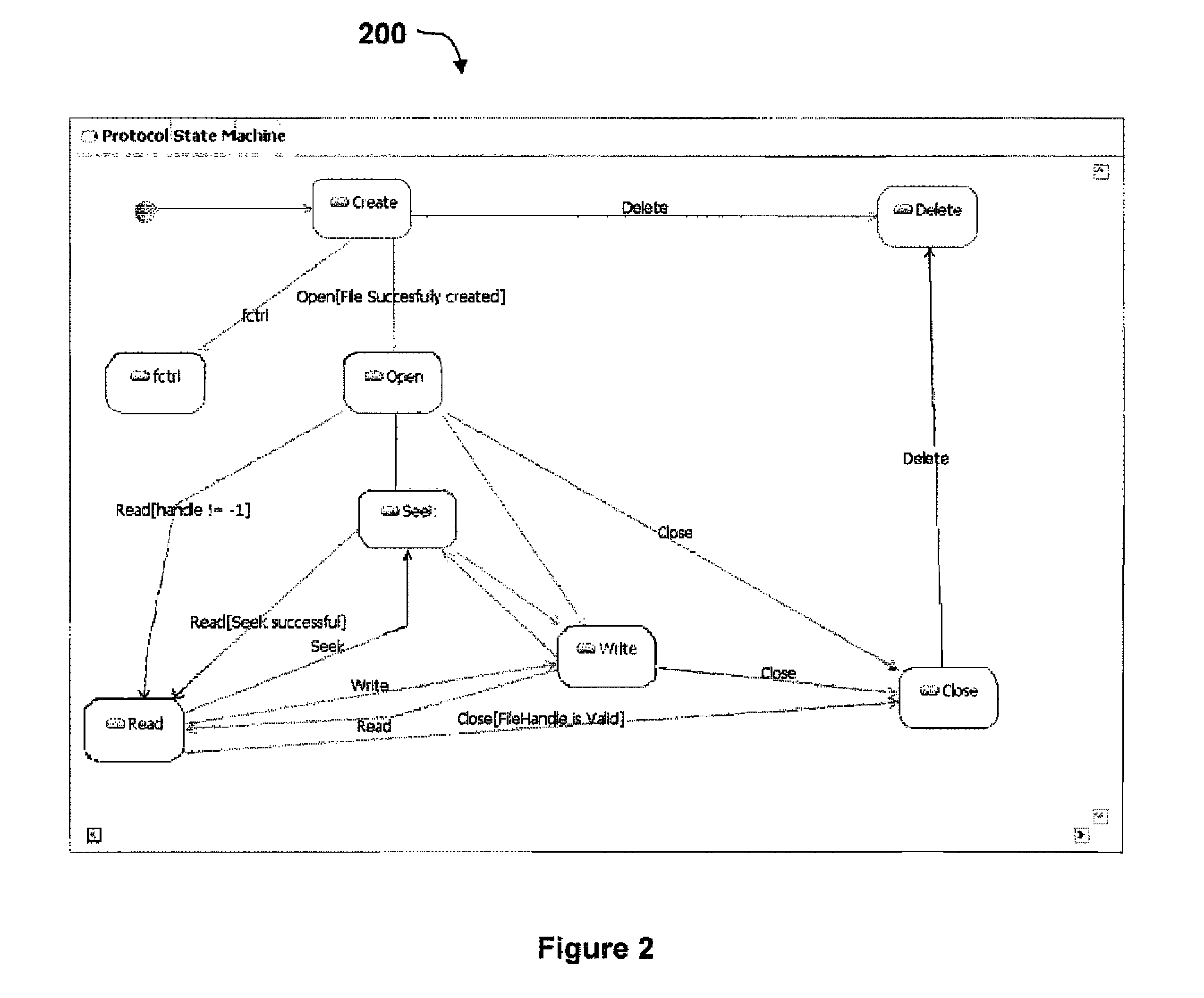
The present invention provides a method and system for creating protocol state machines from software that is currently executing. This involves creating a call graph and values associated with class variables, identifying call patterns, and checking with the sequence of execution of all threads associated in the software. A new protocol state machine is created if the threads do not follow the predefined sequence. The class attributes before and after the call pattern are checked, and the pre and post conditions associated with the class attribute in refining the UML protocol state machine are inferred. This allows for a detailed protocol state machine to be constructed based on the user's interface in a programming language and the level of instrumentation involved.

Problems solved by technology

Software developments have become increasingly large, diverse and complex in recent years.
Because of this, extending the life-span of software has become a challenging problem.
However disordered application of design patterns to a piece of software often makes its design complicated and reduces its performance.
Without a way to improve the method for learning from existing software by a dynamic call graph for creating probable protocol state machines for classes and interfaces, the promise of this technology may never be fully achieved.

Method used


Image

  • Using dynamic call graphs for creating state machines
  • Using dynamic call graphs for creating state machines
  • Using dynamic call graphs for creating state machines

Examples


Embodiment Construction

[0011]Where reference is made in any one or more of the accompanying drawings to steps and / or features, which have the same reference numerals, those steps and / or features have for the purposes of this description the same function(s) or operation(s), unless the contrary intention appears. The term “software”, “program”, “code” and “instruction” are used synonymously. Other equivalent expressions to the above expression would be apparent to a person skilled in the art. The term state machine, protocol state machine, unified modelling language (UML) protocol state machine or UML state machine are used synonymously.

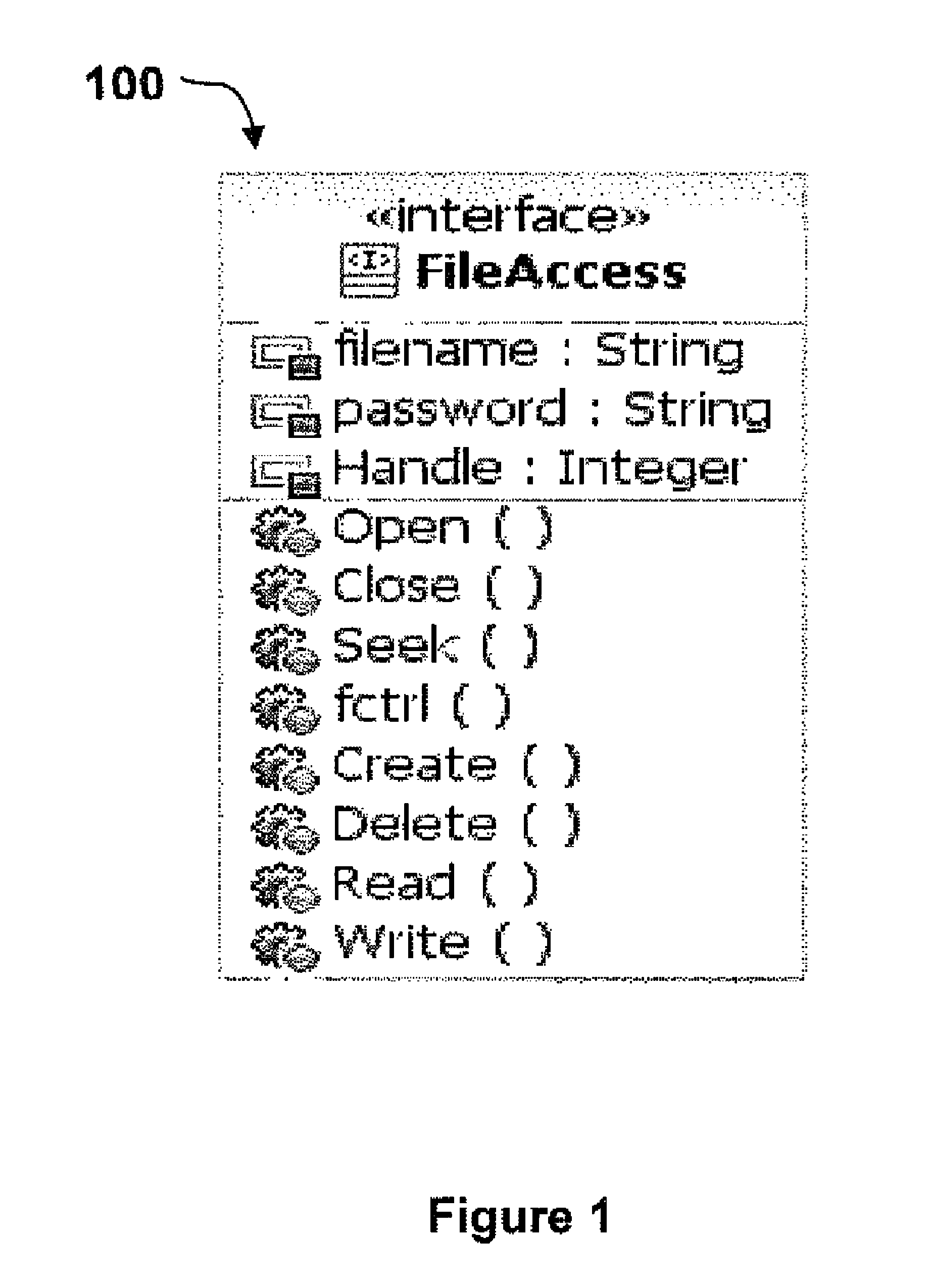
[0012]FIG. 1 illustrates an exemplary embodiment of a file access interface 100. File access interface 100 illustrates that a number of function calls are implemented, preferably during instrumentation. The class variables and the associated values of the class variables are illustrated. For example, file name and password are class variables having string values and handle...


PUM


Abstract

A method and system capable of creating UML protocol state machine for classes and interfaces of a software, by instrumenting the software to obtain a call graph comprising classes and interfaces and respective values associated with class variables and interface variables; identifying particular classes and interfaces in the call graph; identifying call patterns from the call graph to generate a protocol state machine.

Description

FIELD OF THE INVENTION[0001]This invention relates to a method for learning using existing software classes and interfaces and using dynamic call graphs for creating probable protocol state machines for classes and interfaces for the software.BACKGROUND OF THE INVENTION[0002]Software developments have become increasingly large, diverse and complex in recent years. Because of this, extending the life-span of software has become a challenging problem. For example, object-oriented technology offers one solution. By improving the modularity and readability of software it helps us to understand the structure of the software and to maintain, modify and extend it. Various techniques can be used for learning from existing software and such techniques used commonly are adapted to learn various aspects of the software itself and the stages involved in the software development. A commonly used method of learning includes drawing conclusions by users, which includes programmers, designers, test...

Claims


Application Information

Patent Timeline
Patent Type & Authority Patents(United States)
IPC IPC(8): G06F9/44
CPCG06F8/34
Inventor KOHLI, SANDEEP
Owner IBM CORP
Learn More