

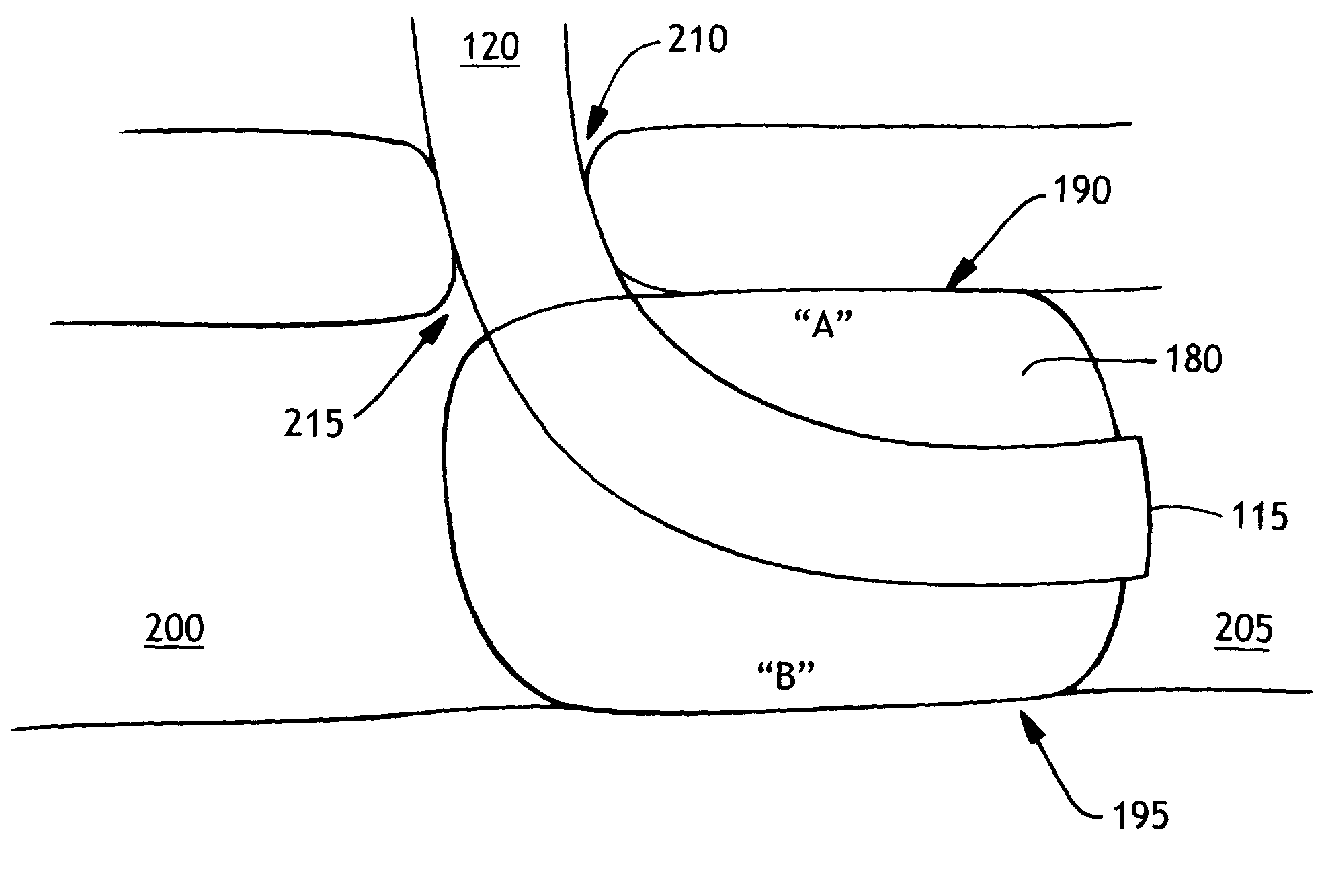
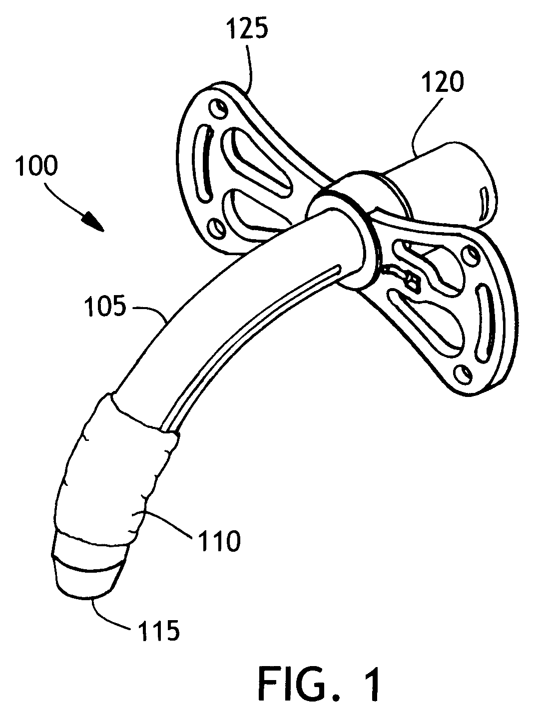
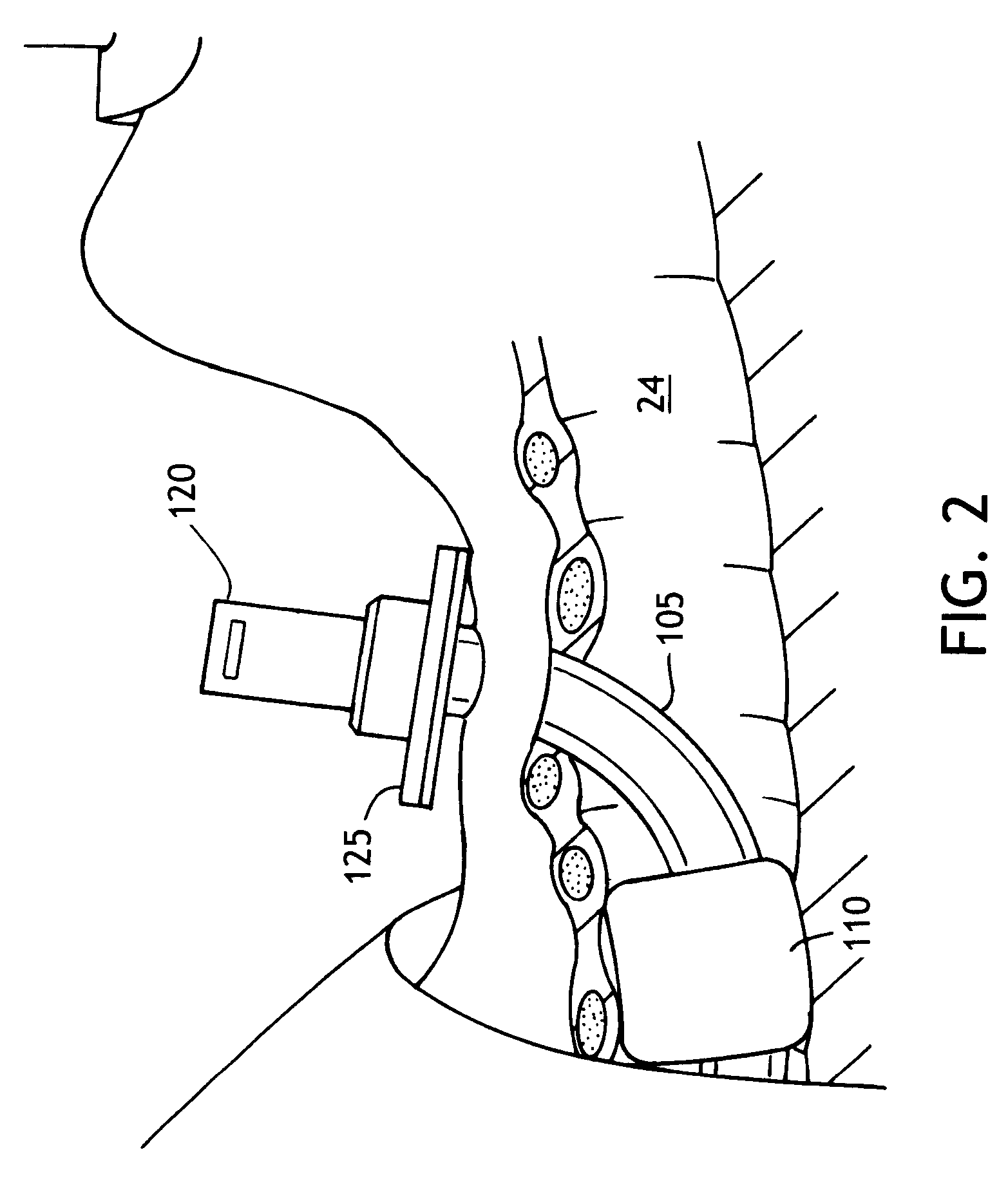
Method of making an improved balloon cuff tracheostomy tube
a tracheostomy tube and balloon cuff technology, which is applied in the direction of dilators, respirators, other domestic articles, etc., can solve the problems of limiting access to the region, affecting the quality of the tracheostomy tube, and affecting the tracheostomy tub
- Summary
- Abstract
- Description
- Claims
- Application Information
AI Technical Summary
Benefits of technology
Problems solved by technology
Method used
Image

Examples
example
[0032]A raw polyurethane tube made from a Dow polyurethane designated Pellethane® 2363-90A which has a durometer hardness of 90A (ASTM D-2240) was used. This polyurethane has a softening temperature of 110° C. (ASTM D-790) and a melt index of 30 g / 10 min. at 224° C., 2160 g (ASTM D-1238). The tube having an 8.61 mm outer diameter (OD) and an inner diameter (ID) of 8.5 mm was placed in a one piece mold with a void space like that of FIG. 4 and clamped at the ends outside the mold. The mold and tubing were preheated to a temperature of about 60° C. Once equilibrium was reached the tubing was stretched by about 75 percent under slight internal pressure; 0.5 bar using nitrogen, in a time of about 10 seconds. The tubing was allowed to retract by about a third as it was internally pressurized at 2 bar to form the balloon. The balloon was heat set at a temperature of about 140° C. for a time of about 90 seconds at a pressure of about 0.5 bar. The balloon was cooled at about 45° C., a vacuu...
PUM
| Property | Measurement | Unit |
|---|---|---|
| temperature | aaaaa | aaaaa |
| temperature | aaaaa | aaaaa |
| pressure | aaaaa | aaaaa |
Abstract
Description
Claims
Application Information