Mounting device having a metallic base plate with multiple hook-like projections obtained by stamping or laser cutting and bending

a technology of metal plate and projection, which is applied in the direction of sheet joining, superstructure connection, application, etc., can solve the problems of not being able to predefine specific shapes for the arrangement of projections, the method of the hook-and-loop closure is not employable for many uses, so as to optimize the overall manufacturing method, simplify the manufacturing process, and simplify the effect of the manufacturing process

Active Publication Date: 2012-11-27
REINZ DICHTUNGS
View PDF22 Cites 12 Cited by
  • Summary
  • Abstract
  • Description
  • Claims
  • Application Information

AI Technical Summary

Benefits of technology

[0026]In a preferred method variation, the hook preforms cut into the base plate are manufactured using a laser beam. By using a laser beam, it is possible to cut even relatively small hook preforms into the metallic base plate precisely and thus achieve the most uniform possible arrangement of the hook preforms.
[0027]Alternatively, it is possible to manufacture the hook preforms cut into the base plate through stamping. This relatively simple metal processing technology simplifies and accelerates the manufacturing procedure, since multiple hook preforms may be stamped out at the same time.
[0028]Furthermore, it is preferable to perform the cutting of the hook preforms and the bending of the hook preforms in a rolling cutting process in a continuous operation or using a progressive die. If the protrusions are produced by bending over a partial area of the bent-out projections, this step may also be performed in this way. In this way, it is possible to execute the different steps of the method in one work cycle and / or by one die, and thus further optimize the overall manufacturing method.

Problems solved by technology

However, these hook-and-loop closures are not employable for many uses, since they do not have the required durability and temperature stability and / or are not electrically conductive.
The texturing of the surface according to this method is therefore relatively difficult and complex.
Furthermore, it is not possible by means of the method to predefine specific shapes for the arrangement of the projections, which would be desirable for tailoring the adhesive properties of the textured surface of the workpiece to the material texture of the workpiece to be connected.

Method used


Image

  • Mounting device having a metallic base plate with multiple hook-like projections obtained by stamping or laser cutting and bending
  • Mounting device having a metallic base plate with multiple hook-like projections obtained by stamping or laser cutting and bending
  • Mounting device having a metallic base plate with multiple hook-like projections obtained by stamping or laser cutting and bending

Examples


Embodiment Construction

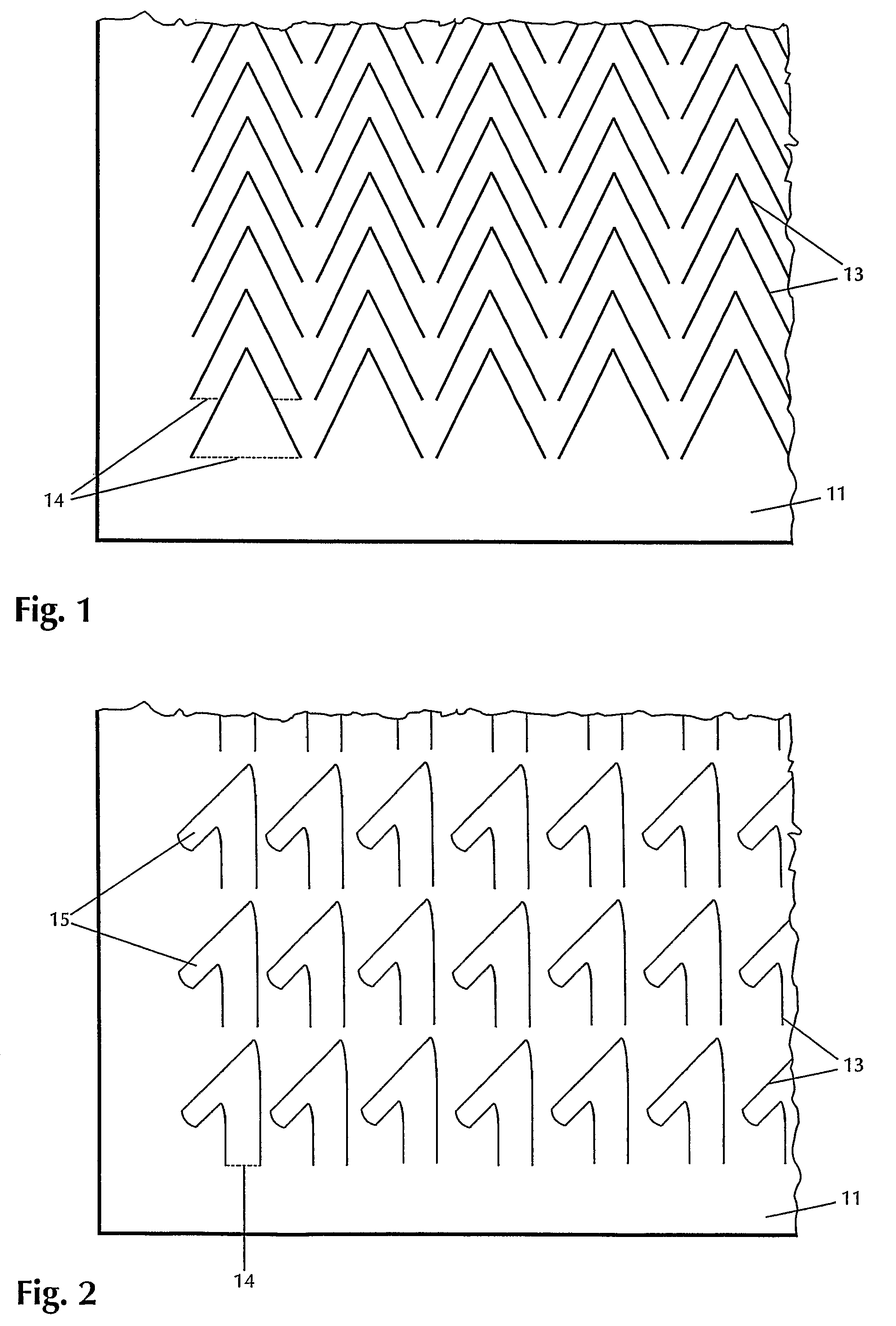
[0056]FIG. 1 shows a partial top view of the base plate 11 of a mounting device according to the present invention having hook preforms 13 cut therein. The hook preforms 13 are arranged V-shaped and nested in one another, so that a relatively high density of hook preforms 13 per unit area is achieved. The V-shaped hook preforms 13 are arranged symmetrically and are nested in one another in such a way that their tips are positioned lying on a straight line within a row. The dashed lines present in two of the hook preforms 13 indicate the bending edges 14, around which the hook preforms 13 are bent in order to thus produce hook-like projections. The bending edge 14 of the hook preform 13 in the lowermost row is arranged as continuous, while the bending edge 14 of the hook preform 13 in the second row is interrupted from below by the nesting of the hook preform 13.

[0057]FIG. 2 also shows a partial top view of a metallic base plate 11 of a mounting device according to the present invent...


PUM

PropertyMeasurementUnit
thicknessaaaaaaaaaa
angleaaaaaaaaaa
angleaaaaaaaaaa

Abstract

The present invention relates to a mounting device having a metallic base plate, from which multiple projections project, and a method for manufacturing this mounting device. The mounting device may be obtained by cutting multiple hook preforms into the surface of the base plate while leaving at least one bending edge per hook preform. Furthermore, hook-like projections are manufactured by bending the hook preforms out of the base plate around the bending edge and possibly lateral protrusions are manufactured on the projections or these are twisted.

Description

BACKGROUND OF THE INVENTION[0001]The present invention relates to a mounting device having a metallic base plate, from which multiple projections project, and a method for manufacturing such a mounting device.[0002]In many industrial and other fields (e.g., construction, automobile construction, domestic use, etc.), it is typically necessary to fix metallic components or workpieces or connect them to other components. In this case, it is frequently desirable to produce the mounts and / or the connections in a simple way which may be performed rapidly, without special tools, such as welding or screwing tools, being necessary for fixing the fasteners. In the field of plastic components, such mounting is for instance achieved by using hook-and-loop closures as fasteners. However, these hook-and-loop closures are not employable for many uses, since they do not have the required durability and temperature stability and / or are not electrically conductive.[0003]A method for manufacturing a m...

Claims


Application Information

Patent Timeline
Patent Type & Authority Patents(United States)
IPC IPC(8): A44B18/00
CPCA44B18/0007A44B18/0015B23K26/38B23P15/00B62D27/06F16B5/07B60R11/00B23K2201/006B23K2201/18Y10T24/2767B60R2011/0063B60R2011/0077Y10T24/2733Y10T24/2792B23K2101/006B23K2101/18
Inventor HOEHE, KURTRUESS, BERNDEGLOFF, GEORGSCHWEIGGART, FRANZ
Owner REINZ DICHTUNGS
Why Eureka
Try Eureka