Device for fixing a reference element

a reference element and device technology, applied in the field of devices and methods for fixing reference elements, can solve problems such as inability to move, and achieve the effect of sufficient stability in attaching devices

Inactive Publication Date: 2012-11-27
BRAINLAB
View PDF32 Cites 3 Cited by
  • Summary
  • Abstract
  • Description
  • Claims
  • Application Information

AI Technical Summary

Benefits of technology

[0008]By means of this device, it is possible to guarantee the attachment of any surgical means to an object such that displacement is not possible. In other words, the attached device can be fixed, in particular to a bone, such that the translational and rotational stability of the location of the device can be guaranteed.
[0012]The first fixing portion can be a bolt, a screw or the like (e.g., a surgical Schanz screw or the like). The diameter of the screw preferably is about 5 mm so as to provide the device with sufficient fixing strength as the first fixing portion is penetrated into the bone (and in particular drilled into the bone). Preferably a bone thickness of at least 4 and preferably 5 mm remains around the insertion point of the screw so as to minimize the likelihood of bone spalling. The screw preferably is drilled monocortically into the bone structure of interest.
[0013]The second fixing portion can have a first segment with a pivoting structure which is close to the coupling structure, such that the first and the second fixing portions may be pivotally coupled to each other. This structure allows the second fixing portion to be rotated or pivoted towards the surface of a bone, such that it is possible to provide another fixing location without serious injury to the bone itself. By means of the first and second fixing portion, it is possible to clamp the bone between them. The first fixing portion, because of the fixing function of the second fixing portion, cannot then be rotated.
[0015]The second fixing portion may be provided with a second lever segment supporting the surface structure that is to be urged against the surface of the bone. An offset segment may be provided between the second lever segment and a first lever segment. This offset segment allows the fixation area for the first fixing portion and the surface structure at one end of the second fixing portion, e.g., of the second lever segment, to be offset. The device described herein can be used for several different bones and bone shapes, and the offset segment can help to adapt the device to different bone shapes.
[0017]A connecting element can be engaged with the first fixing portion, wherein the connecting element can include a protrusion for extending through a recess or hole in the first lever segment. The protrusion may be engaged with a fixing element for urging the surface structure towards the bone surface and for holding the surface structure in this position. The connecting element preferably can be a bushing and the protrusion can be a threaded shaft or pin. The fixing element can be realized as a thumb screw so that a considerable force can be applied by a surgeon without having to use a particular tool.
[0020]A cylindrical bushing can be used achieve a sufficient stability in attaching the device, wherein the bushing can be placed over the Schanz screw. The threaded pin can be connected to the bushing and extend radially outward from the cylinder axis of the bushing, the cylinder axis also being the axis of the screw. The thumb screw or wing nut can be screwed towards the bushing in order to urge the fork towards the Schanz screw, such that the lower or second lever segment with the surface structure is urged against the surface of a bone. This then attaches the device, which provides a considerable resistance against pulling and pushing forces, such that the device can be positioned in a translationally and rotationally stable manner.

Problems solved by technology

By means of this device, it is possible to guarantee the attachment of any surgical means to an object such that displacement is not possible.

Method used


Image

  • Device for fixing a reference element
  • Device for fixing a reference element
  • Device for fixing a reference element

Examples


Embodiment Construction

[0025]In the detailed description that follows, corresponding components have been given the same reference numerals, regardless of whether they are shown in different embodiments of the present invention.

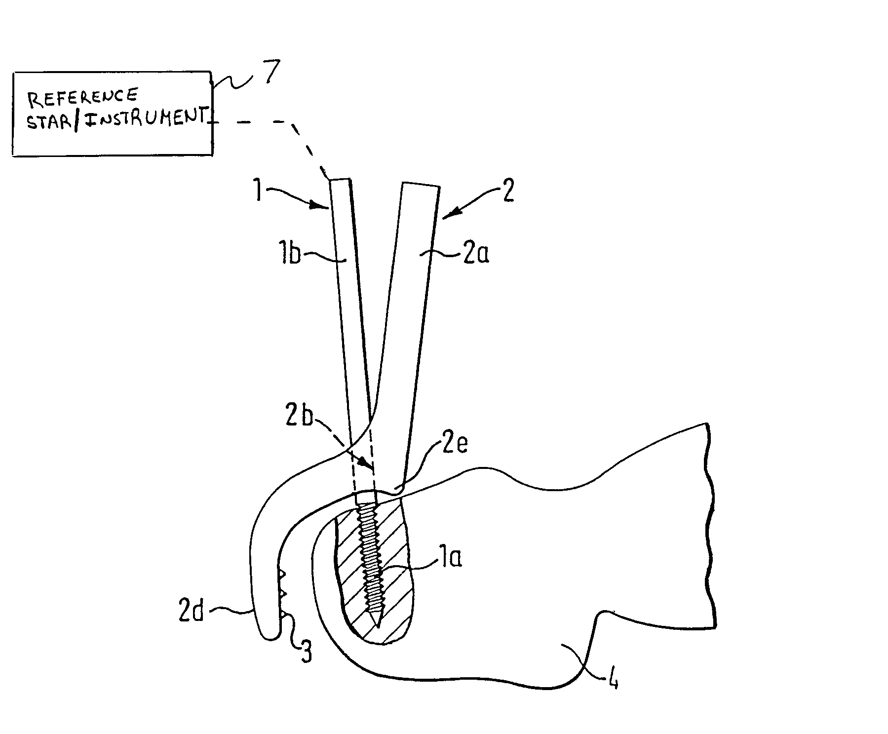
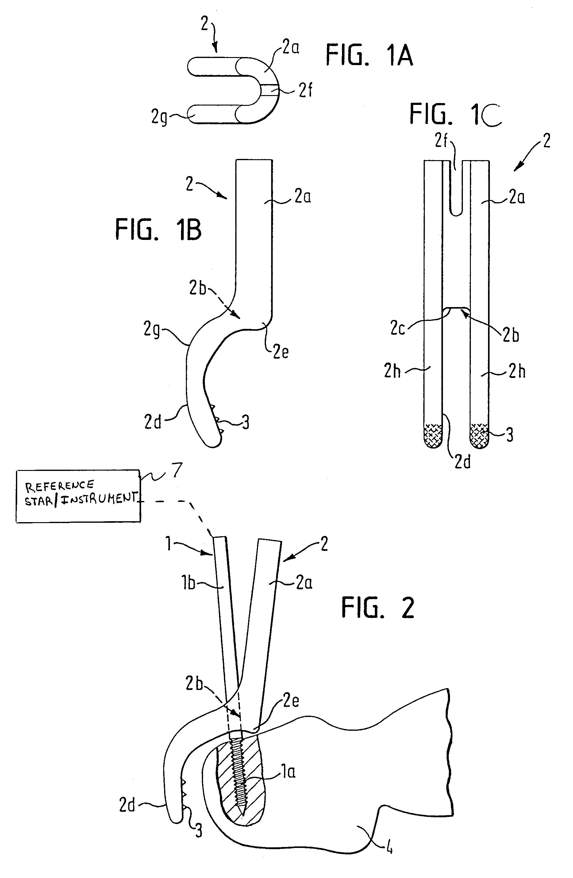
[0026]FIGS. 1A-1C illustrate a second fixing portion 2 of an exemplary fixing device in accordance with the present invention. The second fixing portion 2 has a fork shape, and includes a shaft 2a having a U-shaped cross section. The fork-shaped portion is provided with two prong extensions 2h which comprise the second lever segment 2d of the second fixing portion 2. An upper part of the portion 2 includes the first lever segment 2a. The second lever segment 2d and the first lever segment 2a are connected to each other by an offset segment 2g. On the lower part of the first lever segment 2a, a shoulder segment 2e is provided which, for example, can be shaped like a mandrel or a bolt. A surface structure 3 can be provided at the end of the second lever segment 2d, e.g., at the end o...


PUM


Abstract

A device for fixing a reference element with respect to a field of surgery includes a first fixing portion operable to provide a mechanical resistance against pulling and / or pushing forces, a second fixing portion provided with a surface structure operable to secure the device against an angular force, and a coupling structure. The coupling structure is operative to mechanically couple the second fixing portion to the first fixing portion, wherein said second fixing portion can be pivoted with respect to the first fixing portion.

Description

RELATED APPLICATION DATA[0001]This application claims priority of U.S. Provisional Application Nos. 60 / 754,510 and 60 / 754,553, both filed on Dec. 28, 2005, which are incorporated herein by reference in their entirety.FIELD OF THE INVENTION[0002]The present invention relates to a device and method for fixing a reference element in relation to a surgical field, such as, for example, a human or animal bone.BACKGROUND OF THE INVENTION[0003]Minimally invasive operations require a high degree of accuracy in order to guarantee short hospital stays and quick recovery times. Often in such operations, however, the operations are performed deep within the patient's body and, therefore, the surgeon does not have direct visual access to the surgical workspace. To assist the surgeon in this regard, reference arrays or the like, in conjunction with navigation systems, for example, may be used to provide information and guidance to the surgeon with respect to the surgical workspace. Such reference ...

Claims


Application Information

Patent Timeline
Patent Type & Authority Patents(United States)
IPC IPC(8): F16B9/00
CPCA61B17/8866Y10T403/3986A61B2019/5483A61B2090/3983F16B2/10
Inventor MAIER, CHRISTIANMAIER, GEORG
Owner BRAINLAB
Why Eureka
Try Eureka