Variable inductor

a variable inductor and inductor technology, applied in the direction of variable inductance, continuous variable inductance/transformer, inductance, etc., can solve the problems of restricted use of variable inductor, unnecessary electromagnetic waves are radiated, and magnetic fields are emitted from the inductor, so as to suppress the occurrence of interfering electromagnetic waves, and reduce leakage magnetic flux

Inactive Publication Date: 2012-11-27
SUMIDA CORP
View PDF16 Cites 3 Cited by
  • Summary
  • Abstract
  • Description
  • Claims
  • Application Information

AI Technical Summary

Benefits of technology

[0011]By doing in this manner, the first coil, the second coil and the movable core are involved owing to the magnetic core of the closed magnetic-path structure, so that it is possible to decrease leakage magnetic flux toward the outside and it is possible to make the changing range of the inductance value larger on a situation of suppressing occurrence of interfering electromagnetic waves.
[0012]According to the present invention, the first coil, the second coil and the movable core are involved owing to the magnetic core of the closed magnetic-path structure, so that it is possible to decrease leakage magnetic flux toward the outside and it is possible to suppress occurrence of interfering electromagnetic waves. Then, there is an effect that it is possible to carry out the adjustment of the inductance value easily by moving the movable core.

Problems solved by technology

Conversely, owing to a fact that the variable range of the variable inductor in the past was narrow, it can be said that use application of the variable inductor was restricted to the equipment mentioned above.
However, even if the variable range of the inductance value is wide, when an open magnetic path structure is employed, magnetic fields are emitted from the inductor and unnecessary electromagnetic waves are radiated.
Consequently, in a case in which a plurality of electronic equipment exists mixedly on the periphery of the variable inductor, it sometimes happens, caused by interfering electromagnetic waves, that there is received a bad influence of decrease in function, mis-operation, stoppage, disappearance of record and the like of electronic equipment existing in the vicinity of the variable inductor.
In particularly, in a power supply circuit handling a large electric current, it is not possible to use the variable inductor of the past.
For example, with respect to the variable inductor disclosed in Japanese patent publication No. 2006-286805, the leakage magnetic flux thereof becomes a lot and it easily exerts influence on the outside electronic equipment, so that practicality thereof is poor.

Method used


Image

  • Variable inductor
  • Variable inductor
  • Variable inductor

Examples


Embodiment Construction

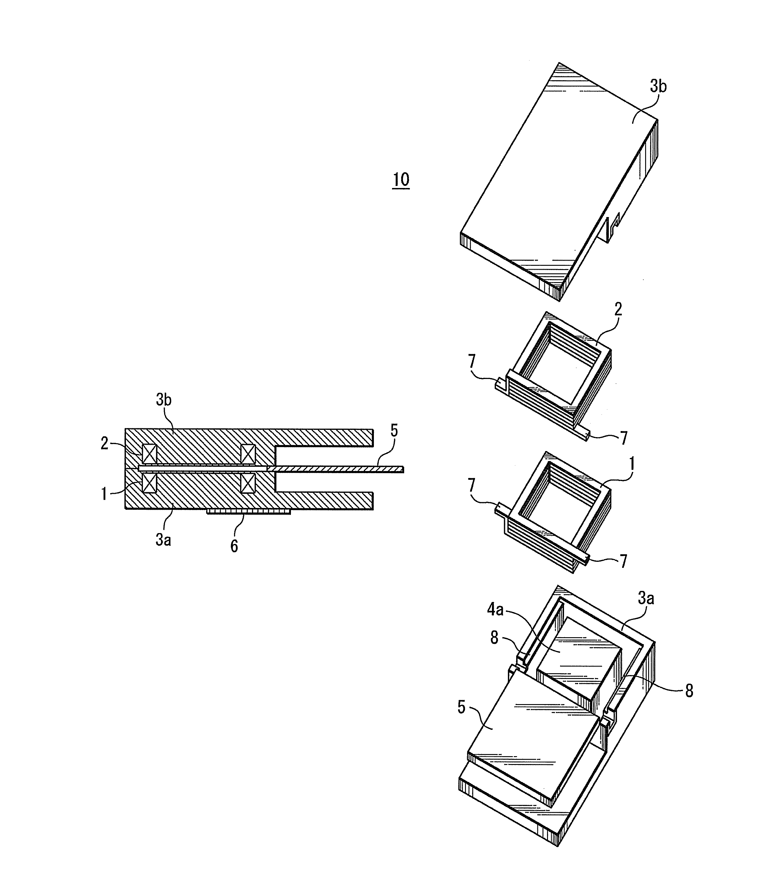
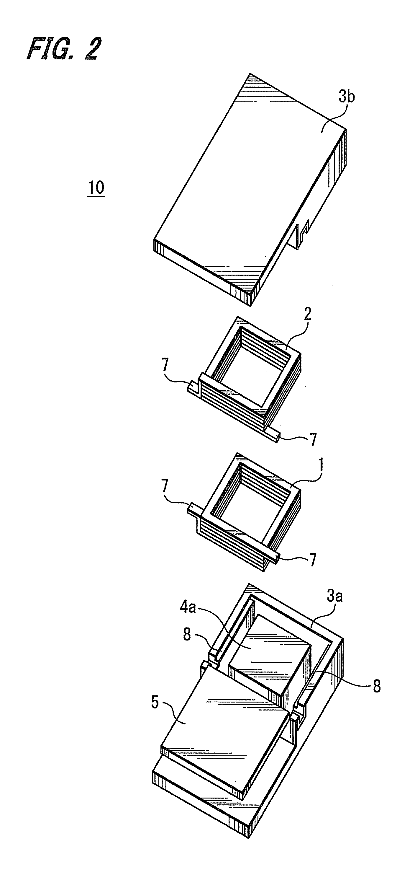
[0026]Hereinafter, it will be explained with respect to a first exemplified embodiment of the present invention with reference to FIG. 1 to FIG. 5. In this exemplified embodiment, it will be explained, for example, with respect to an example applied to a variable inductor 10 which is employed in small sized electronic equipment and electronic circuit.

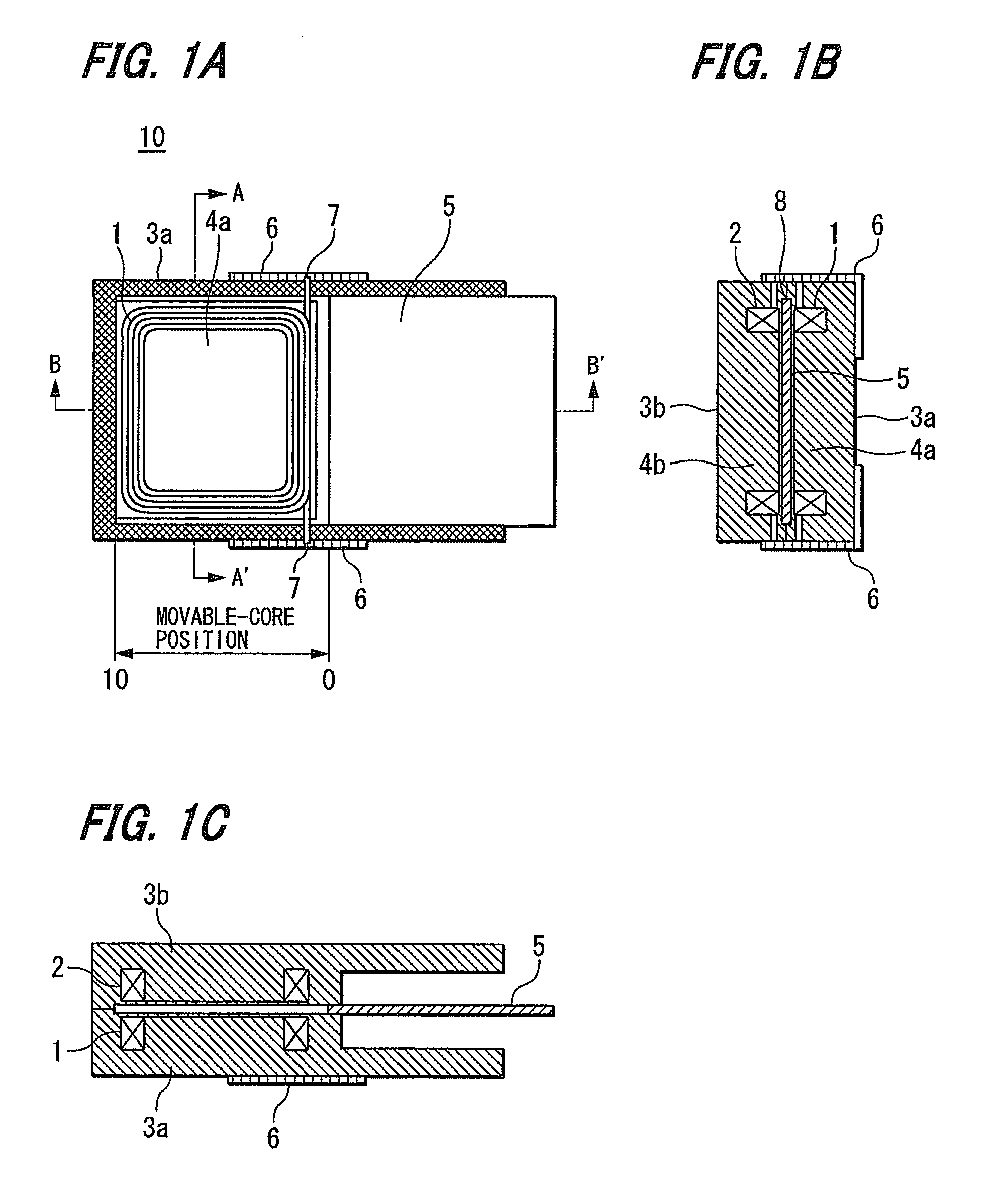
[0027]FIGS. 1A, 1B and 1C show a constitution example of the variable inductor 10.

[0028]FIG. 1A shows a constitution example of the variable inductor 10 in case of being plan-viewed.

[0029]FIG. 1B shows an example of a cross-section diagram along an A-A′ line of the variable inductor 10 in FIG. 1A.

[0030]FIG. 1C shows an example of a cross-section diagram along a B-B′ line of the variable inductor 10 in FIG. 1A.

[0031]The variable inductor 10 includes magnetic-core center-core portions 4a, 4b; and a first coil 1 and a second coil 2 which are formed by a constitution in which the conduction wires thereof are wound-around on the peripheries ...


PUM

PropertyMeasurementUnit
inductanceaaaaaaaaaa

Abstract

A variable inductor includes: a first coil; a second coil which emanates a magnetic flux in a cancelling direction with respect to the magnetic flux generated in the first coil; a plate-shaped movable core positioned between the first coil and the second coil for carrying out opening & closing operation; and first and second magnetic cores, having a closed magnetic-path structure which involves the first coil, the second coil and the movable core. The first magnetic core includes a first center-core portion around which the first coil is wound and the second magnetic core includes a second center-core portion around which the second coil is wound.

Description

CROSS-REFERENCE TO RELATED APPLICATIONS[0001]This application is a continuation of PCT / JP2009 / 065563 filed Sep. 7, 2009, which claims priority to Japanese Application No. 2008-312547 filed Dec. 8, 2008, both of which are hereby incorporated by reference in their entirety.TECHNICAL FIELD[0002]The present invention relate to a variable inductor which is suitable for being applied in a case, for example, in which an inductance value of a coil used in electronic equipment is to be changed.BACKGROUND ART[0003]In the past, there has been a variable inductor in which a position of a magnetic core with respect to a coil is changed by an external signal such that the inductance value of the coil can be changed. Such a variable inductor is used, for example, for adjustment of filter characteristic and resonance frequency in an LC filter and a resonance circuit.[0004]In Japanese patent publication No, 2005-64308, it is disclosed with respect to a variable inductor in which magnetic flux is cha...

Claims


Application Information

Patent Timeline
Patent Type & Authority Patents(United States)
IPC IPC(8): H01F21/06
CPCH01F27/365H01F21/06H01F17/043H01F27/292H01F27/36H01F21/10H01F29/12
Inventor KAWARAI, MITSUGU
Owner SUMIDA CORP
Why Eureka
Try Eureka