
Blind equalization algorithms for adaptive polarization recovery and PMD compensation

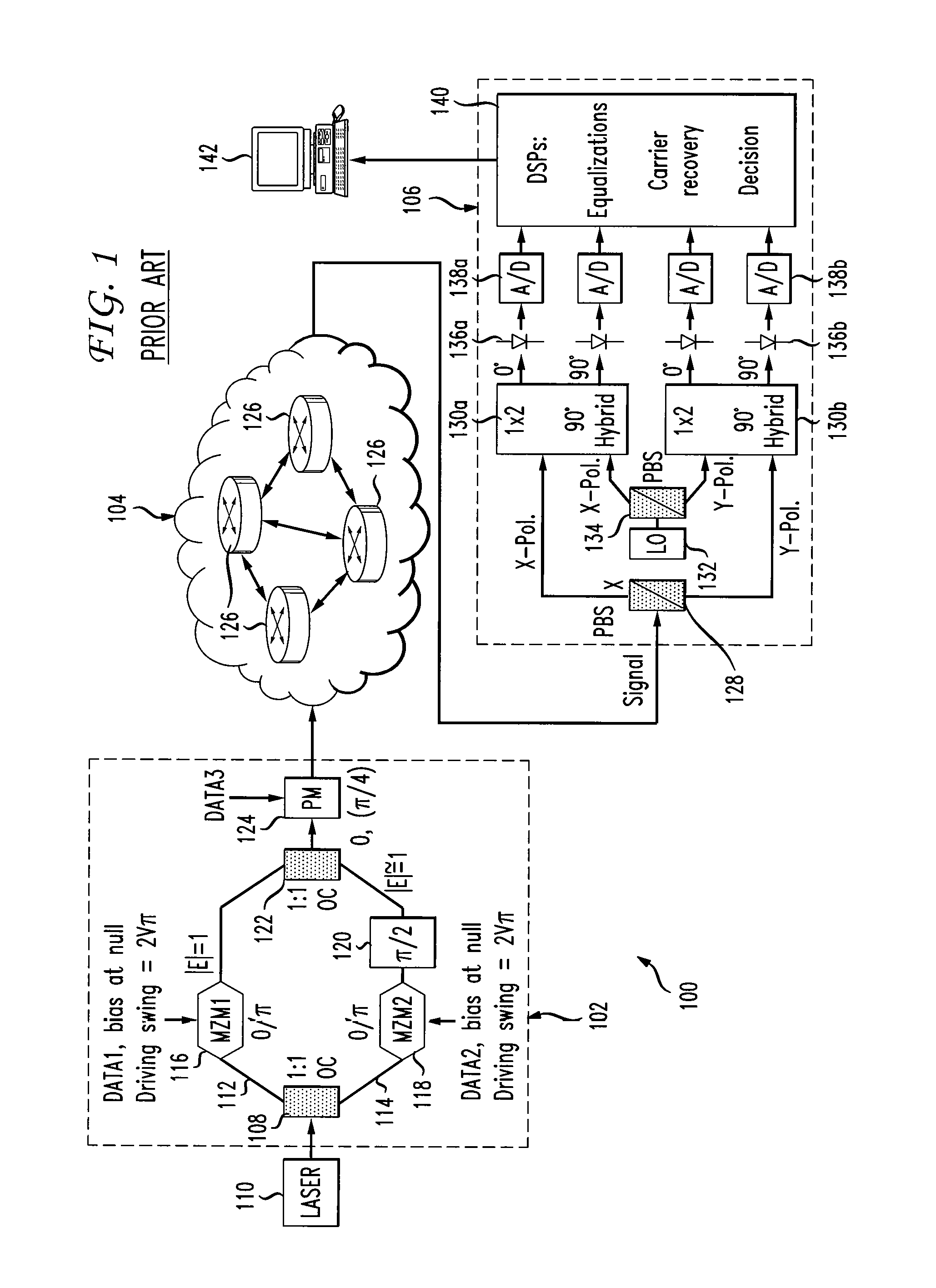
a blind equalization and adaptive polarization technology, applied in the field of communication networks, can solve the problems of extra noise, local minima, and ineffective traditional cma blind equalization algorithm for polarization demultiplexing and pmd compensation

Active Publication Date: 2012-11-27
AT&T INTPROP I LP
View PDF2 Cites 8 Cited by
  • Summary
  • Abstract
  • Description
  • Claims
  • Application Information

AI Technical Summary

Benefits of technology

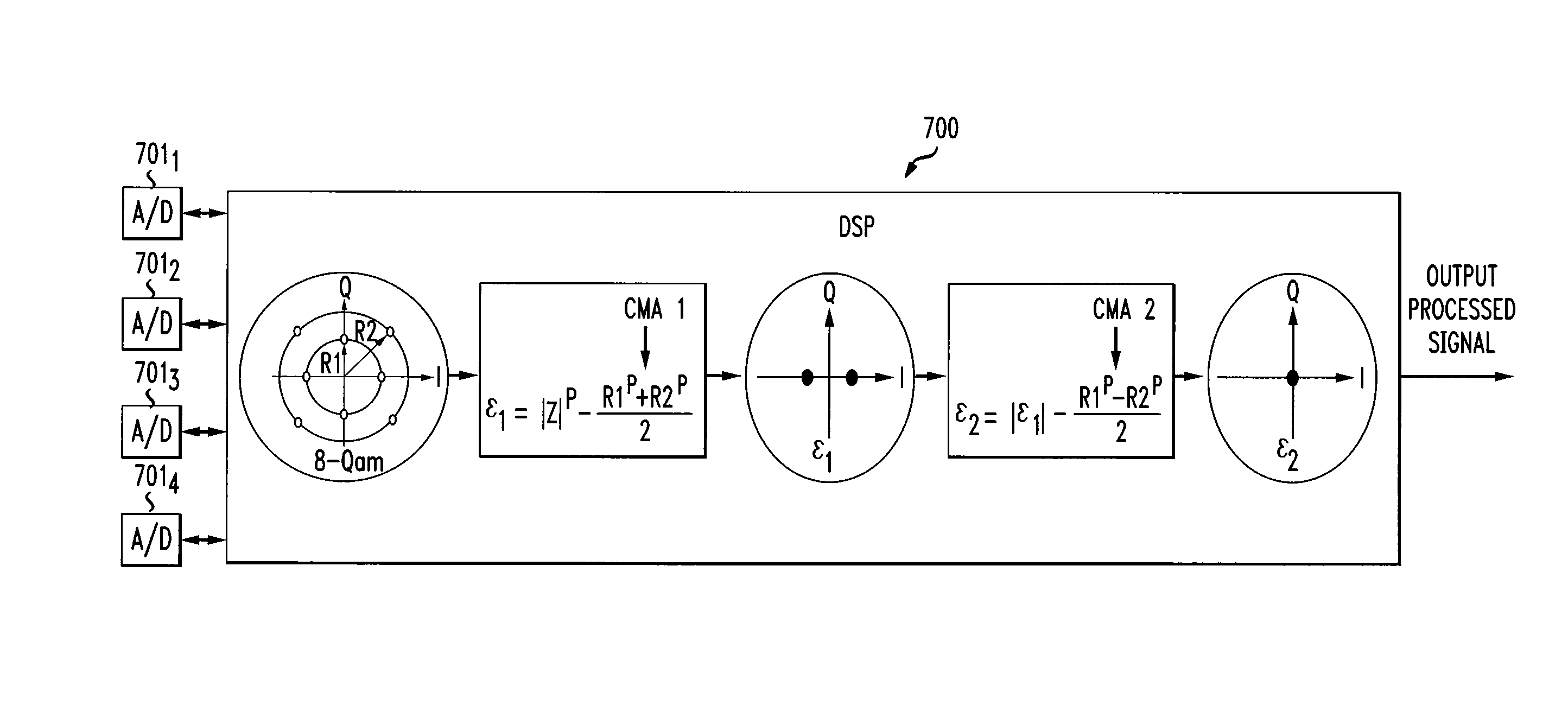
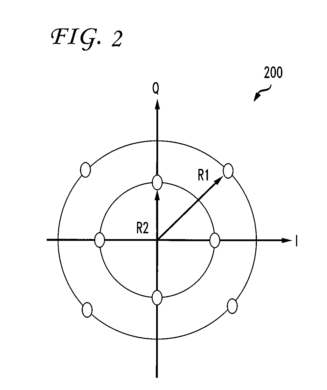
The proposed algorithm effectively compensates for polarization mode dispersion and residual chromatic dispersion, improving signal recovery and reducing noise, as demonstrated by numerical simulations with a 114 Gb / s PDM-8QAM signal, outperforming conventional CMA methods.

Problems solved by technology

For a PDM-M-QAM signal, however, the traditional CMA blind equalization algorithm is not effective for polarization de-multiplexing and PMD compensation.
Non-zero error signals not only leads to extra noise after equalization, but also cause a problem with local minima.

Method used


Image

  • Blind equalization algorithms for adaptive polarization recovery and PMD compensation
  • Blind equalization algorithms for adaptive polarization recovery and PMD compensation
  • Blind equalization algorithms for adaptive polarization recovery and PMD compensation

Examples


Embodiment Construction

[0020]Embodiments of the disclosure will be described with reference to the accompanying drawing figures wherein like numbers represent like elements throughout. Before embodiments of the disclosure are explained in detail, it is to be understood that the disclosure is not limited in its application to the details of the examples set forth in the following description or illustrated in the figures. The disclosure is capable of other embodiments and of being practiced or carried out in a variety of applications and in various ways. Also, it is to be understood that the phraseology and terminology used herein is for the purpose of description and should not be regarded as limiting. The use of “including,”“comprising,” or “having” and variations thereof herein are meant to encompass the items listed thereafter and equivalents thereof as well as additional items.

[0021]In accordance with aspects of the disclosure, a blind equalization algorithm is proposed for adaptive polarization recov...


PUM


Abstract

A device and method are disclosed for blind equalization of an optical signal to implement adaptive polarization recovery, Polarization Mode Dispersion (PMD) compensation, and residual Chromatic Dispersion (CD) compensation in a digital coherent optical communication system.

Description

FIELD OF THE DISCLOSURE[0001]The present disclosure relates generally to communication networks, and more particularly, to a device and method of blind equalization for adaptive polarization recovery, polarization mode dispersion (PMD) and chromatic dispersion (CD) compensation for advanced modulation formats.BACKGROUND[0002]Wave division multiplexing (WDM) optical networks are well known in the art. A WDM channel is typically transmitted by a single mode semiconductor laser. Information to be communicated is imposed on the light by modulating the laser current or by externally modulating the light by applying a voltage to a modulator coupled to the laser source. A receiver employs a photo-detector that converts the light into electric current. Typically, there are two employed methodologies for detecting the received light: direct detection and coherent detection.[0003]Due to the rapid growth of optical networks and the need for greater capacity, significant research has focused on...

Claims


Application Information

Patent Timeline
Patent Type & Authority Patents(United States)
IPC IPC(8): H04B10/06H04B10/12
CPCH04B10/25133H04B10/2569H04B10/6161H04B10/60H04B2210/252
Inventor ZHOU, XIANG
Owner AT&T INTPROP I LP
Learn More