Vein imaging apparatus, positional displacement interpolation method, and program

a positional displacement interpolation and imaging apparatus technology, applied in the field of vein imaging apparatus, can solve problems such as difficulty in producing devices smaller, and achieve the effect of producing smaller devices

Active Publication Date: 2012-11-27
MOFIRIA
View PDF10 Cites 63 Cited by
  • Summary
  • Abstract
  • Description
  • Claims
  • Application Information

AI Technical Summary

Benefits of technology

[0008]In light of the foregoing, it is desirable to provide a vein imaging apparatus, a positional displacement interpolation method, and a program that make it possible to correct a positional displacement between an imaging element and an optical component caused by thermal expansion and to produce the apparatus smaller.
[0019]As described above, according to the embodiments of the present invention, a positional displacement can be corrected between an imaging element and an optical component caused by thermal expansion, and the apparatus can be produced smaller.

Problems solved by technology

As a result, when the technique described in Japanese Patent Application Laid-Open No. 2004-296531 is implemented in a mobile device and the like whose range of operational environment temperature is wide, there is an issue that it is difficult to produce the device smaller.

Method used


Image

  • Vein imaging apparatus, positional displacement interpolation method, and program
  • Vein imaging apparatus, positional displacement interpolation method, and program
  • Vein imaging apparatus, positional displacement interpolation method, and program

Examples


first embodiment

(First Embodiment)

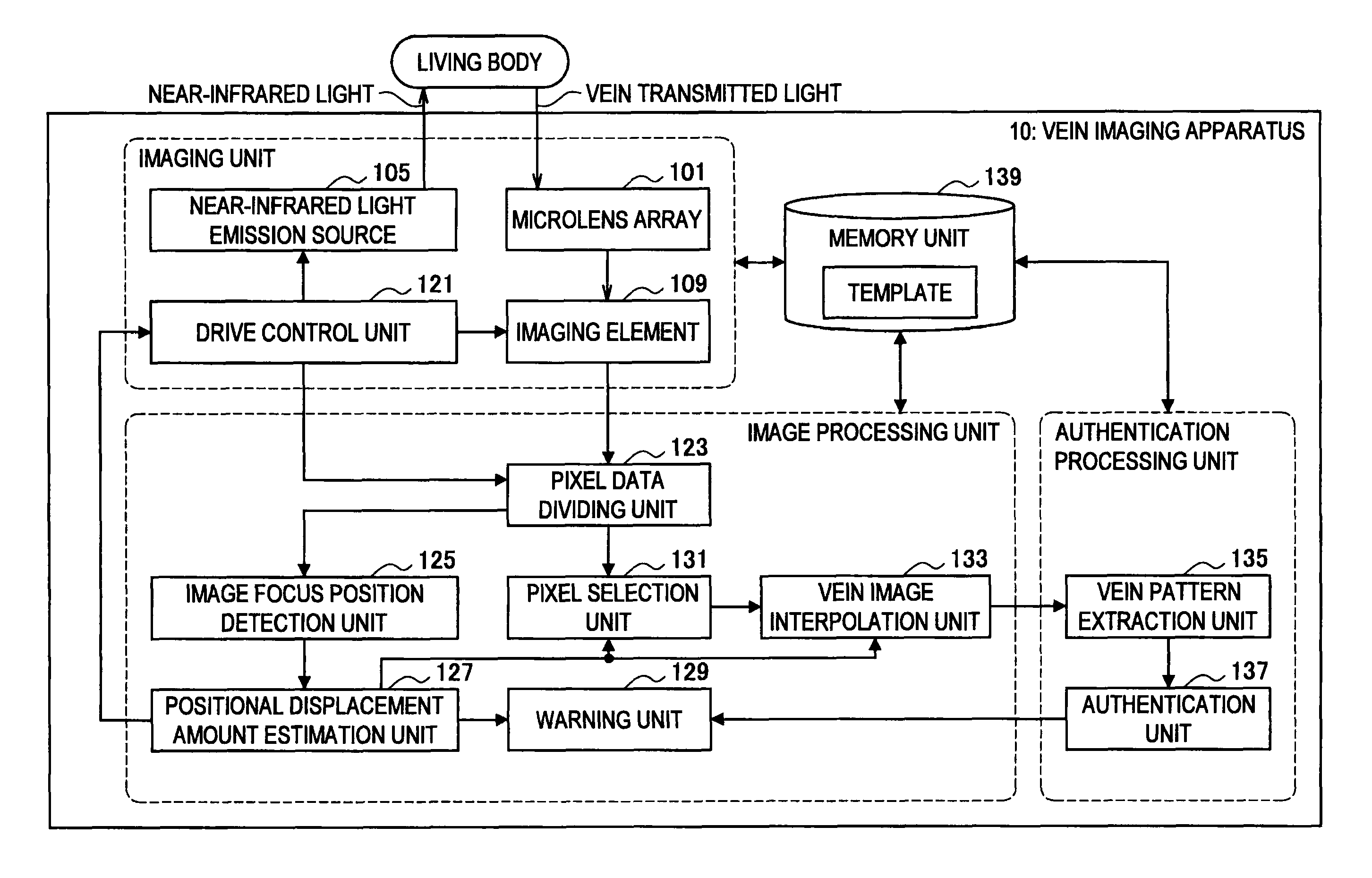
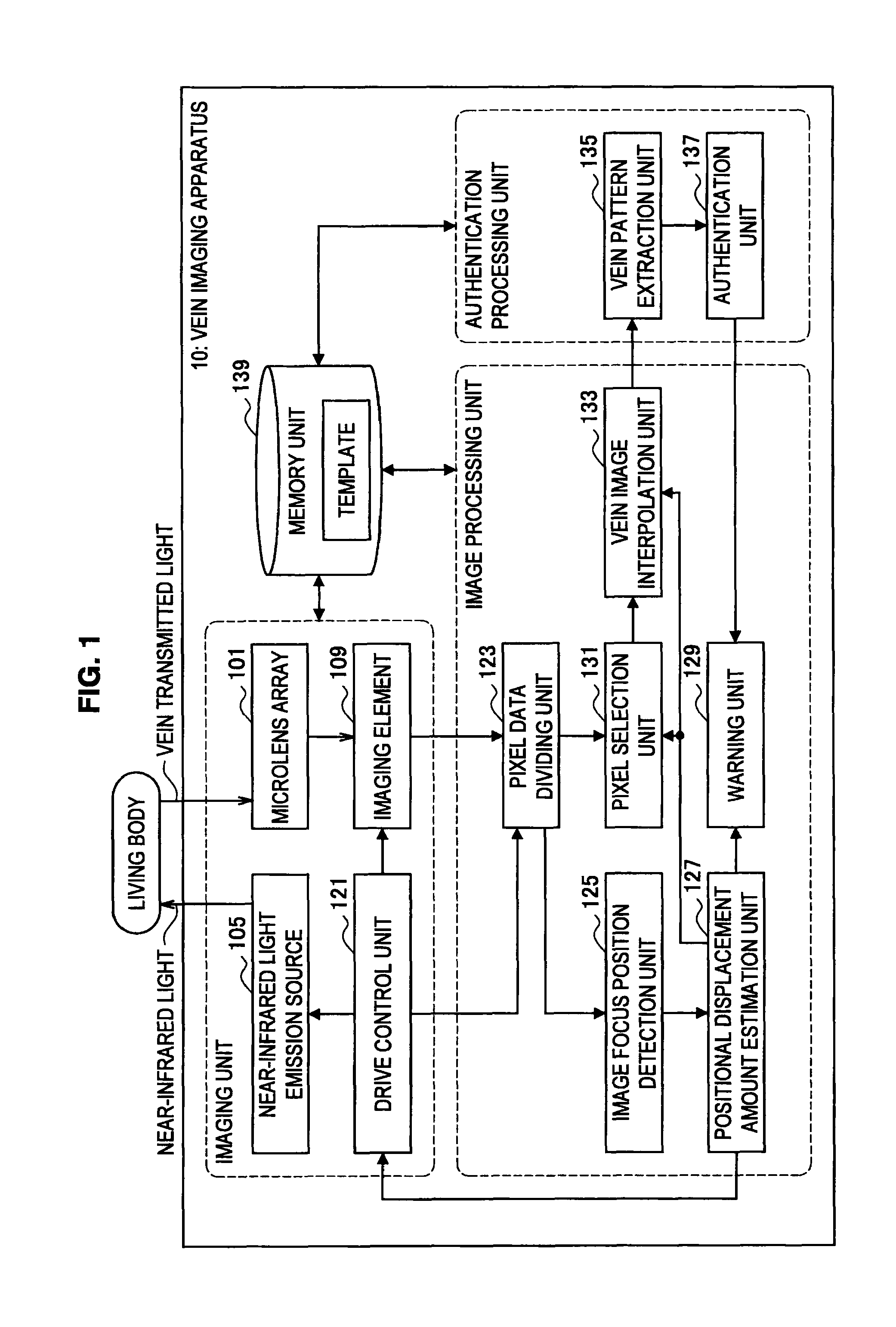
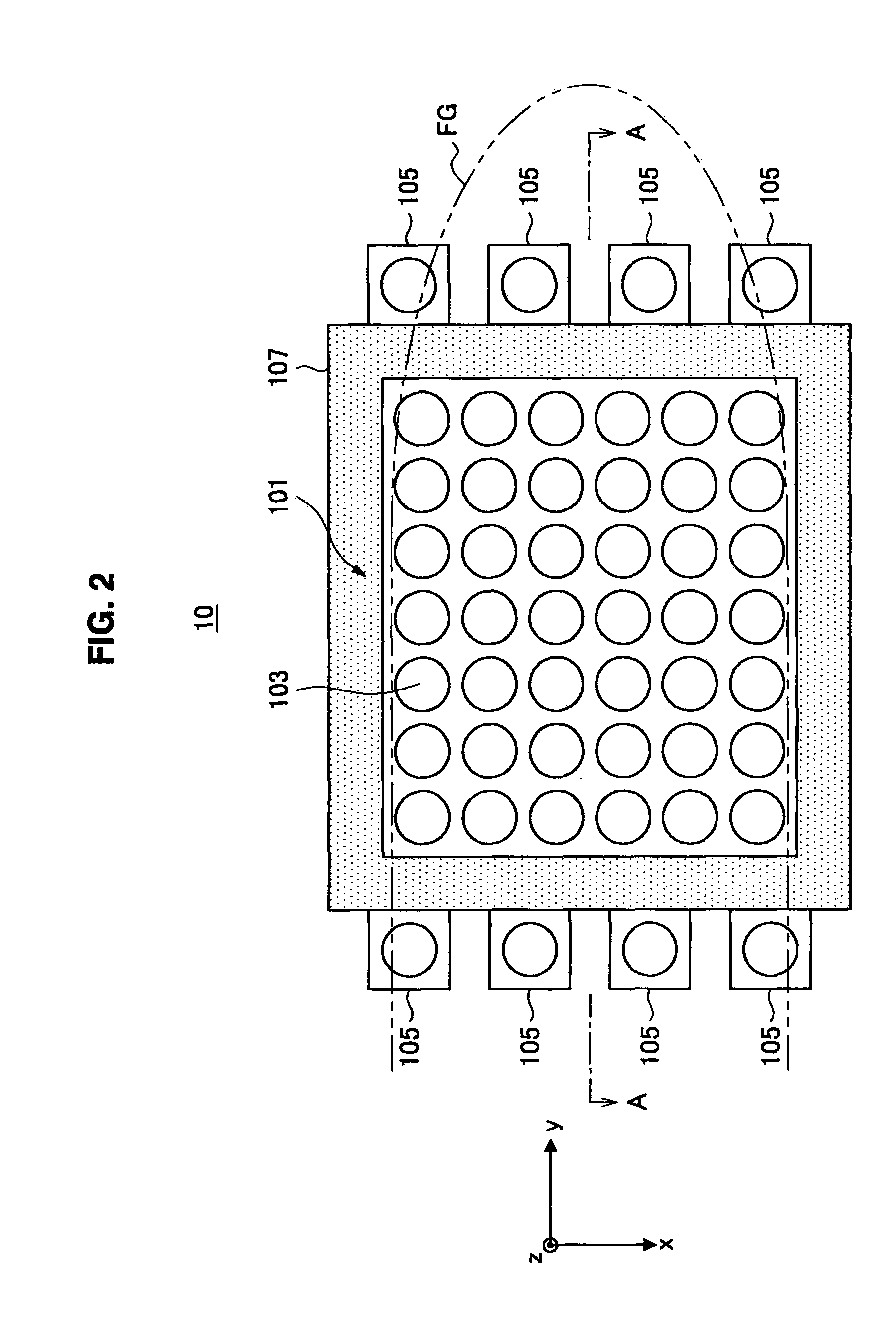
[0063]First, the configuration of the vein imaging apparatus according to the first embodiment of the present invention will be described in detail with reference to FIG. 1 to FIG. 3. FIG. 1 is a block diagram for illustrating the configuration of the vein imaging apparatus according to the present embodiment. FIG. 2 is a plan view of the vein imaging apparatus according to the present embodiment. FIG. 3 is a cross sectional diagram taken along line A-A of FIG. 2.

[0064]As shown in FIG. 1, the vein imaging apparatus 10 according to the present embodiment includes, for example, three units, i.e., an imaging unit, an image processing unit, and an authentication processing unit, and further includes a storage unit 139.

[0065]The imaging unit performs processing of imaging a part of a living body (for example, a finger). As shown in FIG. 1, this imaging unit mainly includes, for example, a microlens array 101, a near-infrared light emission source 105, an imaging element...

second embodiment

(Second Embodiment)

[0161]Next, a configuration of a vein imaging apparatus according to the second embodiment of the present invention will be described in detail with reference to FIG. 12. FIG. 12 is a block diagram for illustrating the configuration of the vein imaging apparatus according to the present embodiment.

[0162]As shown in FIG. 12, the vein imaging apparatus 10 according to the present embodiment includes, for example, three units, i.e., the imaging unit, the image processing unit, and the authentication processing unit. In this embodiment, the imaging unit and the authentication processing unit according to the present embodiment have the same configuration and achieve almost the same effects as the imaging unit and the authentication processing unit of the vein imaging apparatus 10 according to the first embodiment of the present invention, and accordingly, the detailed description thereof is omitted.

[0163]As shown in FIG. 12, the image processing unit mainly includes, ...


PUM


Abstract

An imaging element of a vein imaging apparatus includes a vein image data generation region generating image data of a vein based a near-infrared light that was condensed by a lens array and that was scattered in a living body and transmitted through the vein and a positional displacement detection data generation region that includes a shielded section in which pixels are shielded from the light and an opening section in which pixels are not shielded from the light, and generates data for detecting positional displacement that is used to detect, based on the light received via the opening section, variation in an image focus position according to an imaging temperature. The vein imaging apparatus detects the image focus position of the light and estimates the amount of positional displacement occurred in the apparatus. The vein imaging apparatus selects a pixel based on the obtained amount of positional displacement.

Description

BACKGROUND OF THE INVENTION[0001]1. Field of the Invention[0002]The present invention relates to a vein imaging apparatus, a positional displacement interpolation method, and a program.[0003]2. Description of the Related Art[0004]Biometric individual authentication is highly important technology for protecting the rights in the future network society. In commercial transactions conducted on the Internet in which money, contents, and rights can be stolen any time over the network by means of spoofing, biometric individual authentications particularly attract attention as a technique for protecting a field that may not be protected by encryption alone. However, a biometric individual authentication using fingerprint and iris may not solve the issue of counterfeiting. With regard to this issue, an individual authentication technique using a part of the vein pattern that may not be easily imaged from the outside is expected to be a biometric individual authentication for the next genera...

Claims


Application Information

Patent Timeline
Patent Type & Authority Patents(United States)
IPC IPC(8): H04N5/341H04N5/335H04N1/387G06T1/00A61B6/00G06V40/145
CPCA61B5/117A61B5/489A61B5/0059G06K9/00013A61B2562/0233A61B2562/046G06K2009/00932G06V40/14G06V40/145
Inventor SATO, HIDEO
Owner MOFIRIA
Why Eureka
Try Eureka