Control system

a control system and control technology, applied in adaptive control, process and machine control, instruments, etc., can solve problems such as excessive leakage of working fluid, substantial performance degradation, and increased clearan

Active Publication Date: 2012-11-27
ROLLS ROYCE PLC
View PDF17 Cites 31 Cited by
  • Summary
  • Abstract
  • Description
  • Claims
  • Application Information

AI Technical Summary

Benefits of technology

[0028]This arrangement allows the second variable gain to modify the characteristics of the feedback loop such that phase margins can be improved, engine output overshoots can be reduced, and accurate control of engine speed and acceleration can be achieved, without compromising the bandwidth of the control system. Whilst the engine fuel control system described in U.S. Pat. No. 5,083,277 is focussed on adequate control of NH and NHdot signals and hence compromises on, for example, the performance of intermediate pressure shaft speed (NI) and low pressure shaft speed (NL), the present invention can provide adequate control of all engine outputs, including NI, NL and even modelled / mixed signals NMix and NMixdot disclosed in U.S. Pat. No. 7,111,464.
[0030]Preferably the feedback loop includes an engine model. The engine model may have an inverse static process module which determines steady state fuel flow requirement as a function of steady state engine speed. Thus the feedback loop can mimic accurately the steady state response of the actual engine. The model can account for the effect of external factors, such as altitude, Mach number, guide vane and air bleed settings and power offtake on the characteristics of the engine. Advantageously, the second variable gain can be used to compensate for modelling inaccuracies in the engine model.
[0053]In the case of alternative (b), the control system can be, for example, an engine-casing cooling air control system, or any other fluid flow feedback control system. The cooling air controlled by such a system allows the clearance between the casing and the blade tips of a turbine of the engine to be adjusted, for example to reduce leakage of working fluid between the casing and the tips. More particularly: the aggregate driven quantity demand signal may be an aggregate valve position demand signal; the actuatable component may be a valve which regulates a cooling air flow to an engine casing; the steady state driven quantity requirement value may be a steady state valve position requirement value; the change in driven quantity demand signal may be a change in valve position demand signal; and the reference demand signal may be a cooling air flow demand signal.

Problems solved by technology

Although engine fuel control systems of the type described in U.S. Pat. No. 5,083,277 enable the use of a simple fuel metering valve and can provide accurate control of engine speed and acceleration, under some circumstances, particularly when applied to high bypass ratio turbofans, inadequate control loop stability, in particular phase margins, can result for certain loops when these are tuned to fulfil desired bandwidth requirements.
Substantial performance degradation is caused by the leakage of working fluid between the rotor and stator assemblies of an engine.
At equilibrium conditions, however, the clearance tends to increase and excessive leakage of working fluid can occur through the gaps between rotor and stator assemblies.
Although turbine casing cooling holds considerable promise for improved engine performance, that promise has not yet been fully realised in practice.

Method used


Image

  • Control system
  • Control system
  • Control system

Examples


Embodiment Construction

[0092]Engine Fuel Control System Embodiments

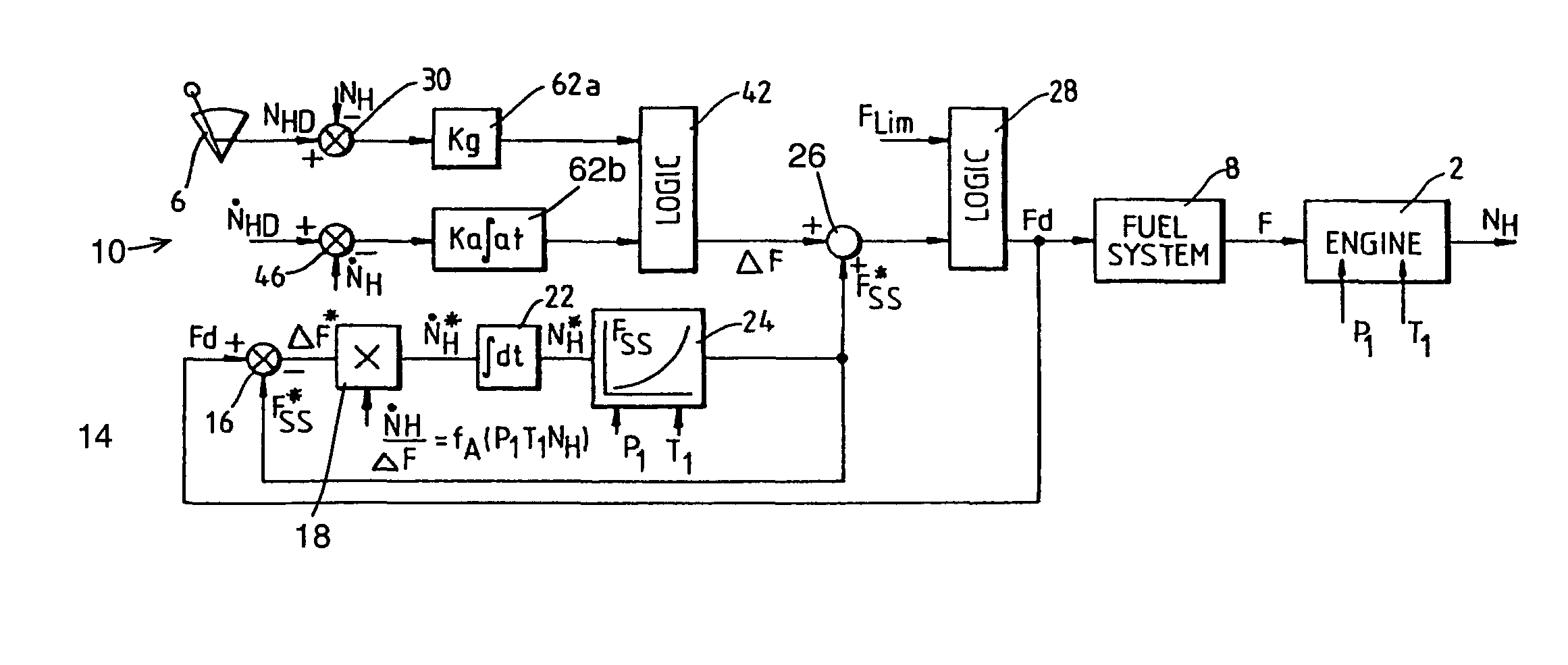
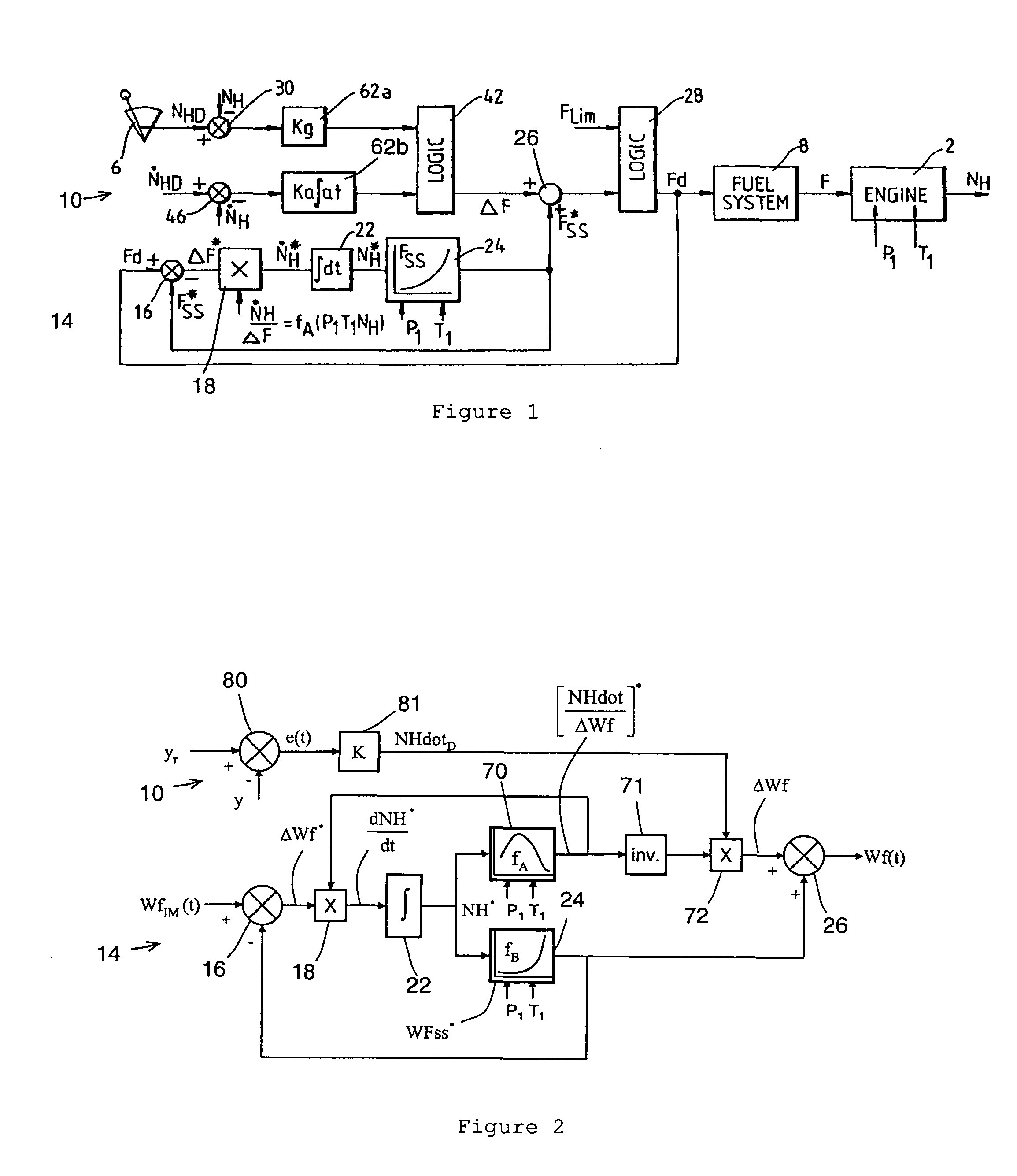
[0093]Before describing engine fuel control system embodiments of the invention, it is helpful to consider in more detail the architecture of an engine fuel control system known as the Rolls-Royce Inverse Model, or RIMM. FIG. 2 shows the structure of the RRIM, which is similar to the engine fuel control system shown in FIG. 1.

[0094]The same reference numbers are used to indicate equivalent features in FIGS. 1 and 2, although in FIG. 2 Wf is used instead of F to indicate a fuel flow requirement, and ΔWf is used instead of ΔF to indicate an overfuelling requirement. To simplify matters, the system downstream from summing junction 26 is omitted from FIG. 2. The signal generator 6, engine speed error circuit 30 and acceleration limiter loop comparator 46 are replaced by a generic control error circuit 80 representing any control loop. The signal “yr” is a vector of the reference values of the controlled engine outputs (corresponding to the NHD...


PUM


Abstract

A control system provides an aggregate driven quantity demand signal for controlling an actuatable component. The system has a summing junction which generates the aggregate driven quantity demand signal by summing a first output signal, which converges on a steady state driven quantity requirement value, and a change in driven quantity demand signal. The system further has a feedback loop which generates the first output signal in response to the aggregate driven quantity demand signal. The system also has a first variable gain which tunes the change in driven quantity demand signal in response to a reference demand signal. The feedback loop includes a second variable gain which tunes the rate at which the first output signal converges on the steady state driven quantity requirement value. Typically, the reference demand signal corresponds to a desired value or desired change in value of a parameter which is itself varied or controlled by actuation of the actuatable component.

Description

FIELD OF THE INVENTION[0001]The present invention relates to control systems, such as engine fuel control systems or engine-casing cooling air control systems, particularly for gas turbine engines.BACKGROUND OF THE INVENTION[0002]A purpose of an engine fuel control system is to provide an engine with fuel in a form suitable for combustion and to control the rate of fuel flow for accurate control of engine speed and acceleration. It is known to control the thrust of a gas turbine engine using an Electronic Engine Control (EEC), the thrust of the engine being indirectly measured using shaft speed, Engine Pressure Ratio (EPR) or Turbine Power Ratio (TPR). The EEC also controls (i) the shaft speeds within safe operational limits, and (ii) the temperature and pressure at different parts of the engine to avoid undesirable conditions such as surge or stall, and to ensure the integrity of the engine. Environmental considerations as well as growing power demands of modern aircraft require co...

Claims


Application Information

Patent Timeline
Patent Type & Authority Patents(United States)
IPC IPC(8): G06F19/00
CPCF01D11/24F02C9/28G05B5/01G05B13/024F05D2270/304
Inventor MAHMOOD, SHAHID
Owner ROLLS ROYCE PLC
Why Eureka
Try Eureka