Method for providing an energy assisted magnetic recording head in a wafer packaging configuration

a technology of energy-assisted magnetic recording and wafer packaging, which is applied in the manufacture of head surfaces, record information storage, instruments, etc., can solve problems such as heat dissipation problems

Active Publication Date: 2012-12-04
WESTERN DIGITAL TECH INC
View PDF22 Cites 153 Cited by
  • Summary
  • Abstract
  • Description
  • Claims
  • Application Information

AI Technical Summary

Problems solved by technology

Consequently, heat dissipation may be problematic.
Fabrication of the components of the transducers 27 / 27′ and 28 / 28′ is increasingly challenging at smaller sizes.

Method used


Image

  • Method for providing an energy assisted magnetic recording head in a wafer packaging configuration
  • Method for providing an energy assisted magnetic recording head in a wafer packaging configuration
  • Method for providing an energy assisted magnetic recording head in a wafer packaging configuration

Examples


Embodiment Construction

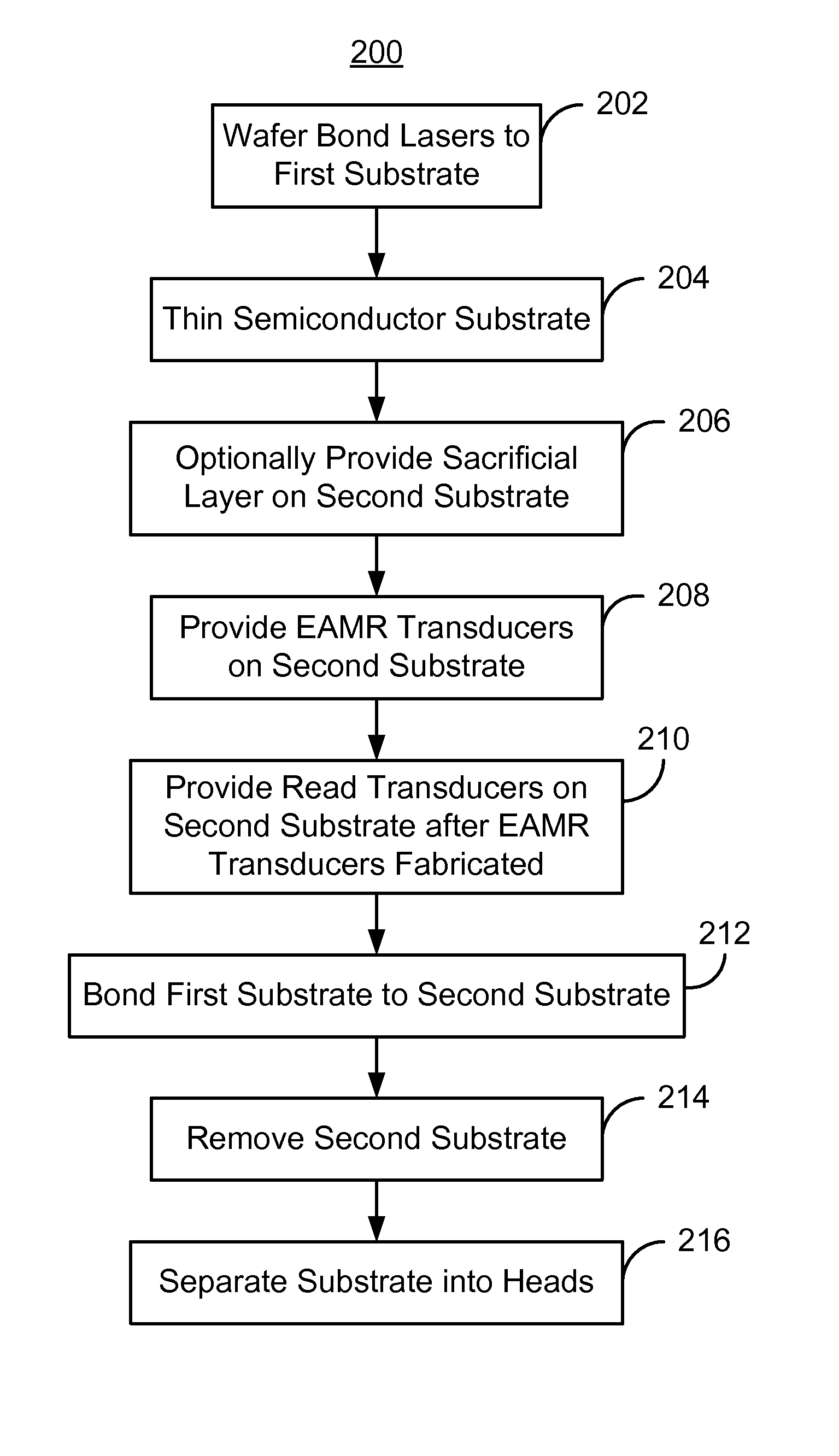
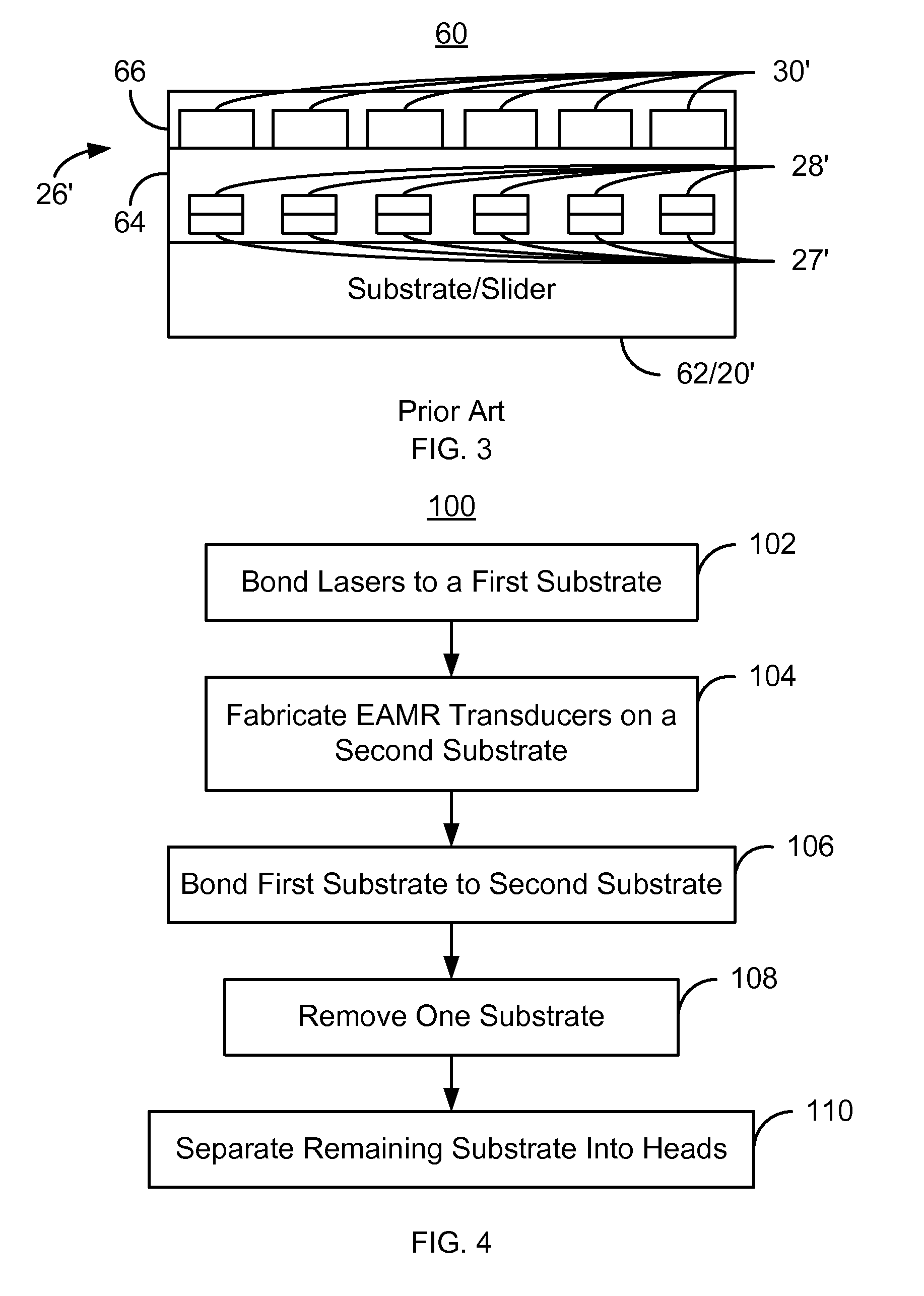
[0019]FIG. 4 is a flow chart depicting an exemplary embodiment of a method 100 for fabricating EAMR heads. Although certain steps are shown, some steps may be omitted, interleaved, performed in another order, and / or combined. In addition one or more of the steps may include substeps. The EAMR heads being fabricated may be part of merged heads, each of which includes an EAMR write transducer, a read transducer and resides on a slider.

[0020]A plurality of lasers are bonded to a first substrate, via step 102. In some embodiments, step 102 is accomplished by wafer bonding a semiconductor substrate, such as GaAs, to the first substrate. Multiple lasers have been fabricated on the semiconductor substrate. Alternatively, a semiconductor substrate may be cleaved into bars. These bars, each of which includes multiple lasers, may be wafer bonded to the first substrate. Thus, the lasers need not be individually bonded to the first substrate. In other embodiments, the lasers might not be formed...


PUM

PropertyMeasurementUnit
heightaaaaaaaaaa
widthaaaaaaaaaa
widthaaaaaaaaaa

Abstract

A method for providing energy assisted magnetic recording (EAMR) heads is described. The method comprises bonding a plurality of lasers to a first substrate. The plurality of lasers corresponds to the plurality of EAMR heads and is for providing energy to a plurality of EAMR transducers. The method further comprises fabricating the plurality of EAMR transducers for the plurality of EAMR heads on a second substrate, bonding the first substrate to the second substrate such that the plurality of EAMR transducers and the plurality of lasers reside between the first substrate and the second substrate, removing at least one of the first substrate and the second substrate, and separating a remaining substrate into the plurality of EAMR heads.

Description

BACKGROUND[0001]FIG. 1 depicts a side view of portion of a conventional energy assisted magnetic recording (EAMR) disk drive 10. The conventional EAMR disk drive 10 includes a recording media 12, a conventional slider 20, and a conventional laser diode 30 that are typically attached to a suspension (not shown). The conventional slider 20 has a leading edge 22, a trailing edge 26, and a back side 24. The leading edge 22 and trailing edge 26 are so termed because of the direction the conventional media 12 travels with respect to the EAMR transducer 28. In addition to the conventional EAMR transducer 28, the slider also includes a conventional read transducer 27. Other components that may be part of the conventional EAMR disk drive 10 are not shown. The conventional slider 20 is typically attached to the suspension at its back side 24. A conventional EAMR transducer 28 is coupled with the slider 20.[0002]The laser diode 30 is coupled in proximity to the EAMR transducer 28 on the traili...

Claims


Application Information

Patent Timeline
Patent Type & Authority Patents(United States)
IPC IPC(8): G11B5/127H04R31/00
CPCG11B5/314G11B5/3173Y10T29/49043Y10T29/49083Y10T29/49044G11B2005/0021
Inventor YI, GEYUAN, HONGXINGSUN, MINGWAN, DUJIANG
Owner WESTERN DIGITAL TECH INC
Why Eureka
Try Eureka