Method for providing a wrap-around shield for a magnetic recording transducer

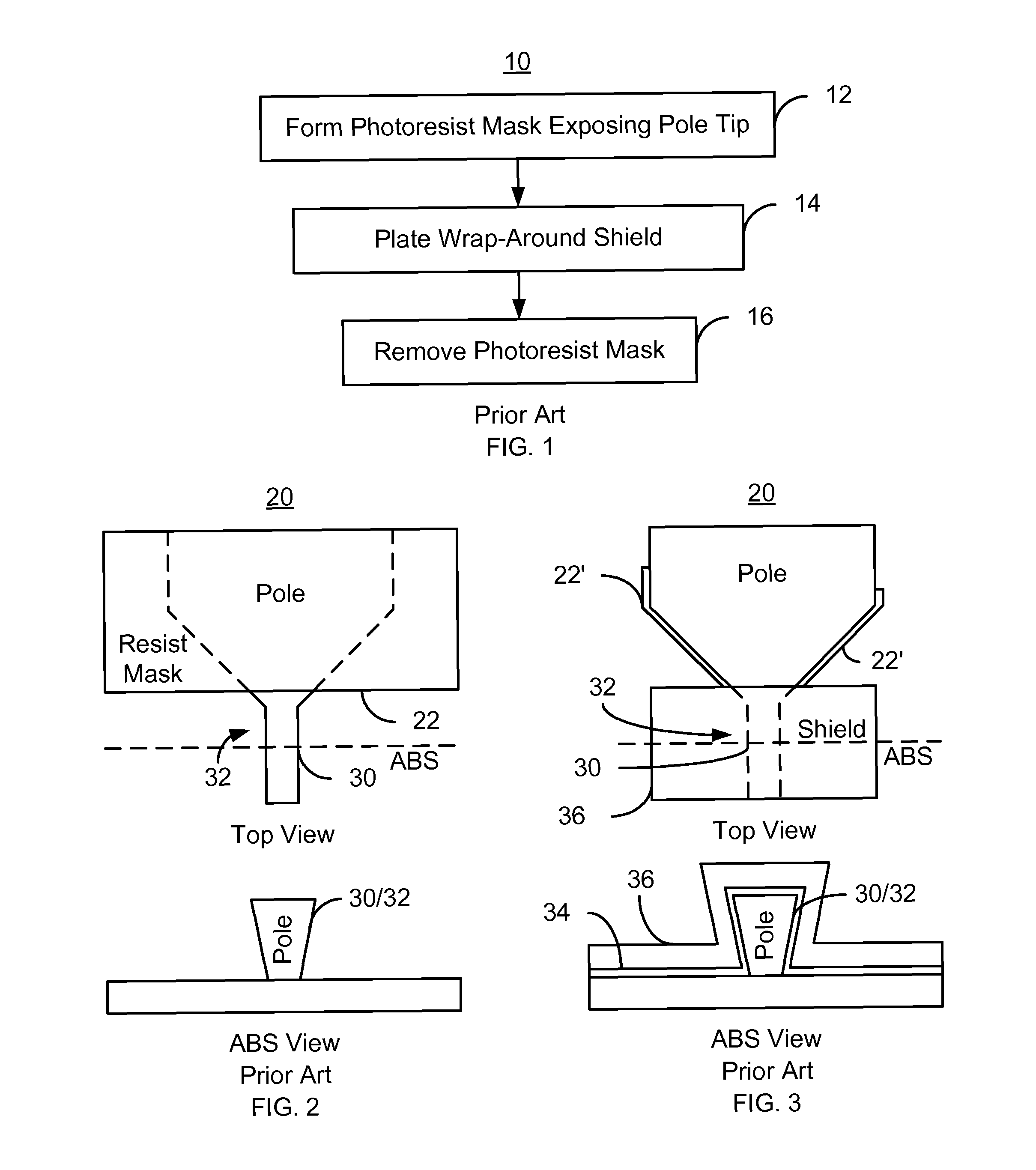
a technology of magnetic recording transducer and wrap-around shield, which is applied in the direction of manufacturing head surfaces, instruments, manufacturing tools, etc., can solve the problems of adversely affecting the performance and/or reliability of the conventional magnetic transducer, round the sidewalls of the conventional pole b>30/b>, and be unreliable in manufacturing

Active Publication Date: 2012-12-04
WESTERN DIGITAL TECH INC
View PDF5 Cites 152 Cited by
  • Summary
  • Abstract
  • Description
  • Claims
  • Application Information

AI Technical Summary

Benefits of technology

[0006]FIG. 1 is a flow chart depicting a conventional method for fabricating a wrap-around shield.
[0007]FIG. 2 depicts a con

Problems solved by technology

Upon lapping, the photoresist residue 22′ may result in defects in the conventional magnetic transducer 20.
These defects may adversely affect performance and/or r

Method used


Image

  • Method for providing a wrap-around shield for a magnetic recording transducer
  • Method for providing a wrap-around shield for a magnetic recording transducer
  • Method for providing a wrap-around shield for a magnetic recording transducer

Examples


Embodiment Construction

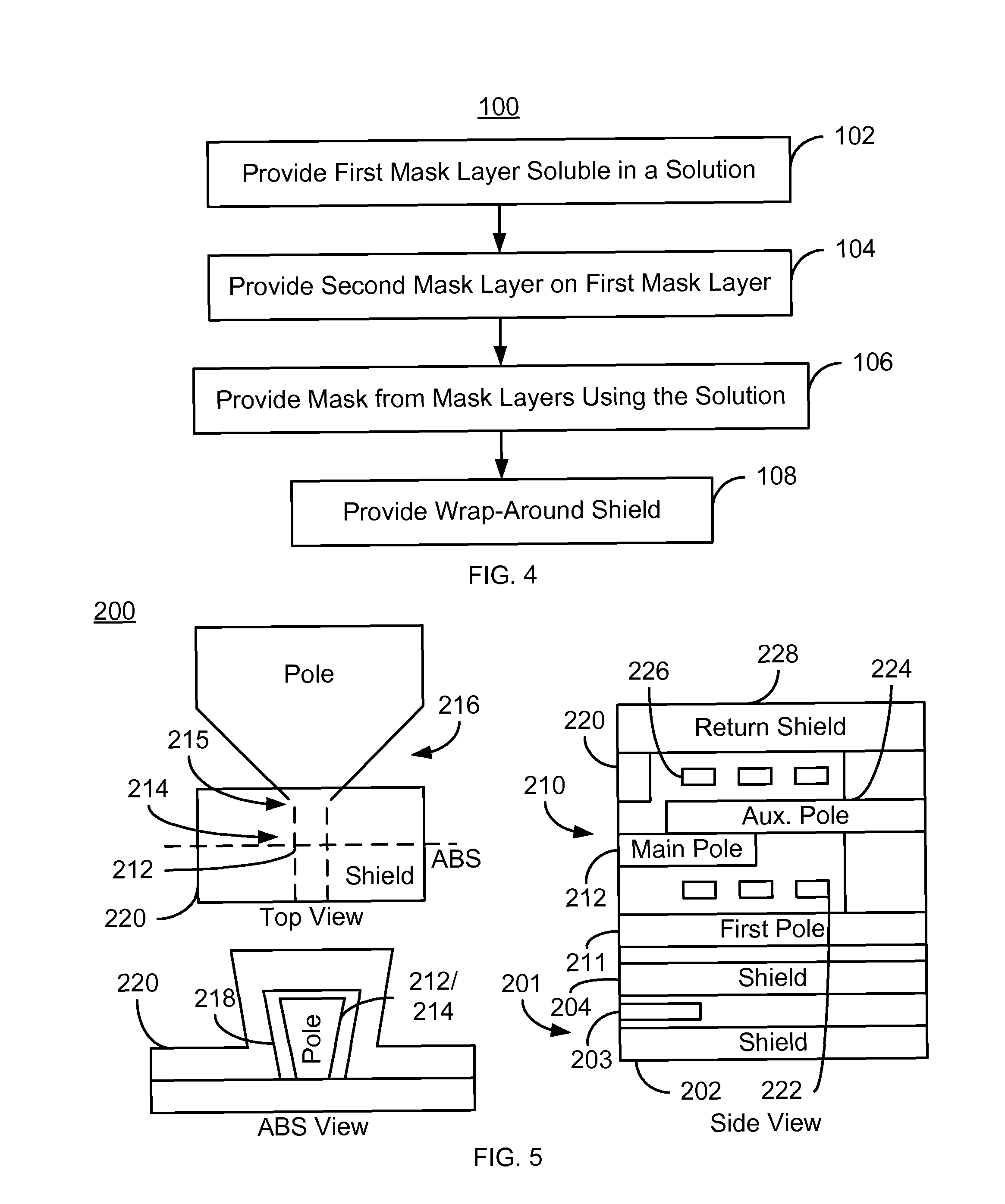
[0013]FIG. 4 is a flow chart depicting an exemplary embodiment of a method 100 for fabricating a wrap-around shield for a magnetic recording transducer. For simplicity, some steps may be omitted. Although described in the context of providing a single magnetic transducer, the method 100 may be used to fabricate multiple transducers at substantially the same time. The method 100 is also described in the context of particular structures. A structure or layer may include multiple materials and / or multiple sub-layers and may be formed using multiple sub-steps. The method 100 also may start after formation of other portions of the transducer. For example, the method 100 may commence after formation of a pole, coil(s), and shields. In some embodiments, the pole is trapezoidal in shape, as viewed from the ABS. As the magnetic transducer may be part of a merged head including a read transducer, the method 100 may start after formation of a read transducer.

[0014]A first mask layer is provide...


PUM

PropertyMeasurementUnit
Thicknessaaaaaaaaaa
Thicknessaaaaaaaaaa
Thicknessaaaaaaaaaa

Abstract

A method for fabricating a magnetic transducer is described. The magnetic transducer includes a pole having a pole tip and a flared region. The method Includes providing a first mask layer on the pole and providing a second mask layer on the first mask layer. The first mask layer is soluble in a predetermined solution and has a first thickness. The second mask layer has a second thickness greater than the first thickness. The method also includes forming a mask from the first mask layer and the second mask layer. The step of forming the mask layer includes using the predetermined solution. The mask has a pattern that exposes a portion of the pole tip and covers a portion of the flared region. The method also includes providing a wrap-around shield on at least the pole tip.

Description

BACKGROUND[0001]FIG. 1 depicts a conventional method 10 for providing a wrap-around shield. FIGS. 2-3 depict top and air-bearing surface (ABS) views of a conventional magnetic recording transducer 20 during fabrication using the method 10. Referring to FIGS. 1-3, the method 10 commences after the pole has been formed. A photoresist mask that covers a portion of the pole is fabricated, via step 12. Step 12 simply includes providing a layer of photoresist directly on the conventional transducer 20, exposing portions of the photoresist layer to light, then immersing the photoresist in a developer. Thus, the portion of the photoresist layer that has been exposed to light is removed. FIG. 2 depicts the conventional transducer 10 after step 12 is completed. Thus, the pole 30 and photoresist mask 22 are shown. The pole 30 includes a pole tip region 32, which is exposed by the photoresist mask 22. The remaining portion of the pole 30 is, however, covered by the photoresist mask 22.[0002]A w...

Claims


Application Information

Patent Timeline
IPC IPC(8): G11B5/127H04R31/00
CPCG11B5/1278G11B5/3116G11B5/315G11B5/3163Y10T29/49044Y10T29/49052Y10T29/49048Y10T29/49046Y10T29/49041
Inventor ZENG, XIANZHONGHUANG, YUNHEWANG, LINGSUN, HAI
Owner WESTERN DIGITAL TECH INC
Why Eureka
Try Eureka