Vertical axis wind turbine and method of installing blades therein

a vertical axis, wind turbine technology, applied in vessel construction, renewable energy generation, greenhouse gas reduction, etc., can solve the problems of large resistance produced on the blade, inability of the wind rotor to reach higher rotating speeds, and difficulty in starting, so as to avoid the vibration of the motor and avoid the load of the wind rotor

Active Publication Date: 2012-12-04
YAN QIANG
View PDF27 Cites 3 Cited by
  • Summary
  • Abstract
  • Description
  • Claims
  • Application Information

AI Technical Summary

Benefits of technology

[0024]In other aspects of the invention, in order to overcome the negative effects on the motor due to horizontal vibrations resulting from coaxial connection of vertical axis and motor, the motor in this invention adopts a hollow rotating shaft so that the rotating axis of wind rotor passes through the motor's hollow shaft and is connected with the base, thus avoiding the loading weight of the wind rotor to the rotating axis of the motor. Adopting a direct connection of the vertical axis to the base rather than a coaxial connection to the motor avoids vibrations of the motor.

Problems solved by technology

This resulted in a starting difficulty but allowed the wind rotor to attain a high rotating speed.
Alternatively, the radius / chord ratio was set to be very small, which allowed for an easy rotor starting but resulted in a large resistance produced on the blade during the rotation of the wind rotor at a very high wind speeds; thus, the wind rotor was unable to reach higher rotating speeds.
Therefore, the conventional designs could neither make the motor obtain a large enough torque nor rotate at a sufficiently high speed.
This affects the wind energy utilization ratio of vertical axis wind turbine and lowers the commercial value of conventional vertical axis wind turbines.
But, in an actual wind field, the force impact on the wind rotor consisting of blades is very complicated and in particular, a very strong centrifugal force is produced during high-speed rotation.
Thus, the safety of blades connected to the support arm using the above methods cannot be ensured and blade fracture or detachment from the support arm may occur.
But the wind rotor encounters a very large force impact in an actual wind field, which inevitably produces a horizontal vibration on the vertical axis, and thus adversely effects the operation of the rotor.

Method used


Image

  • Vertical axis wind turbine and method of installing blades therein
  • Vertical axis wind turbine and method of installing blades therein
  • Vertical axis wind turbine and method of installing blades therein

Examples


example 1

Determination of Rotating Speed and Power by CFW under Different Radius / Chord Ratios

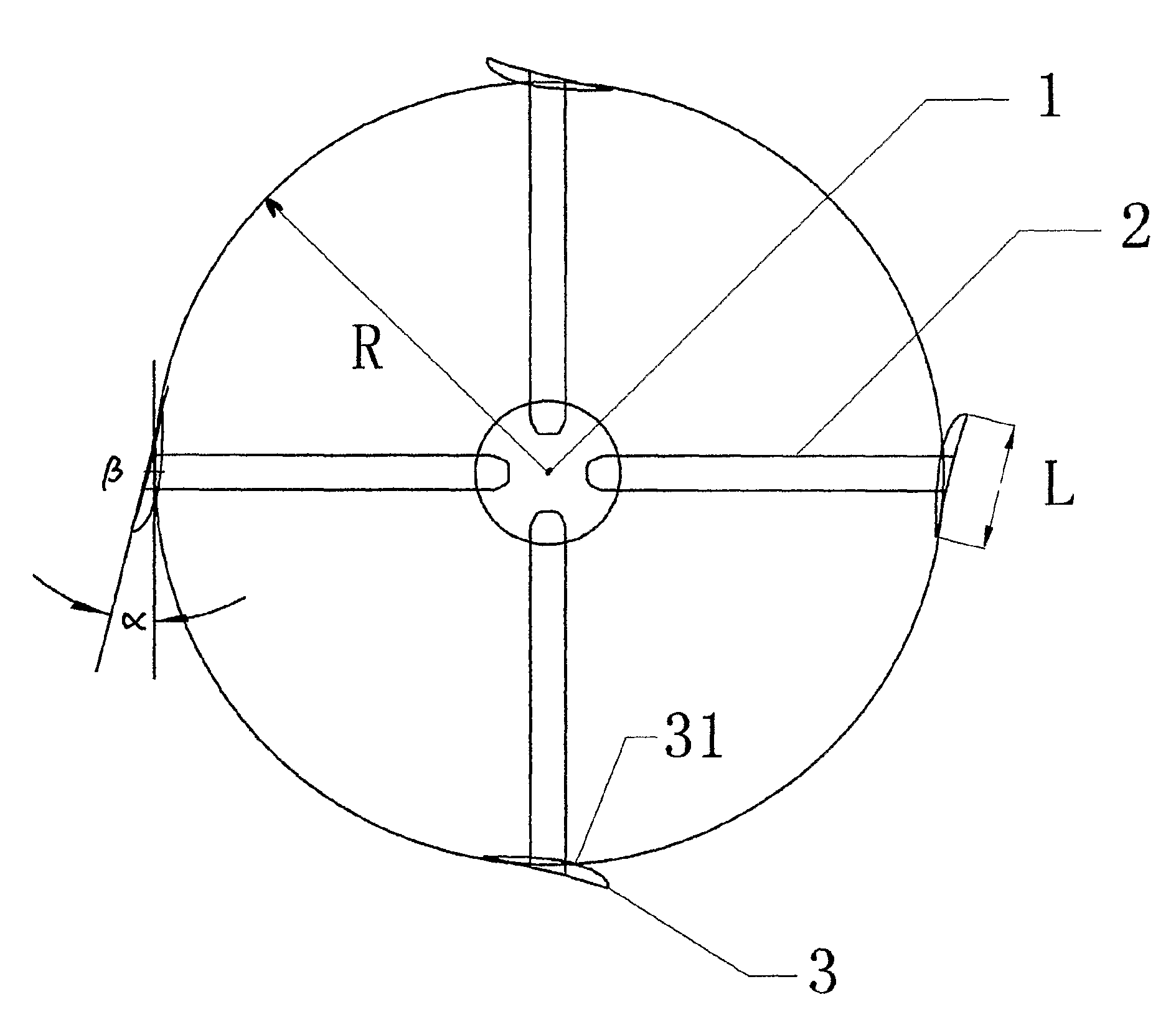
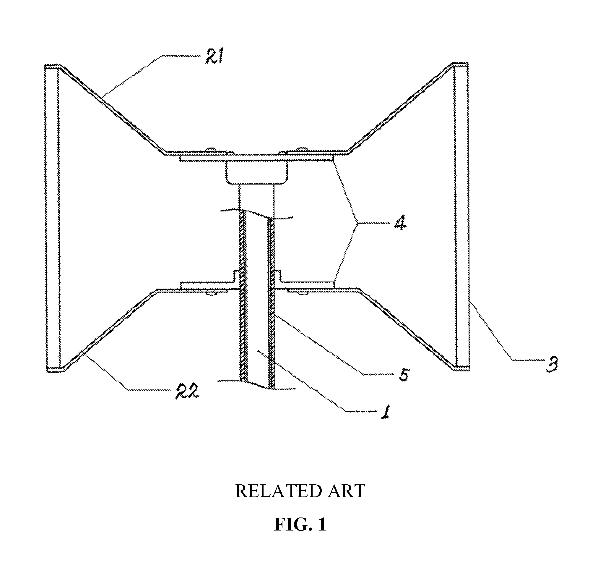
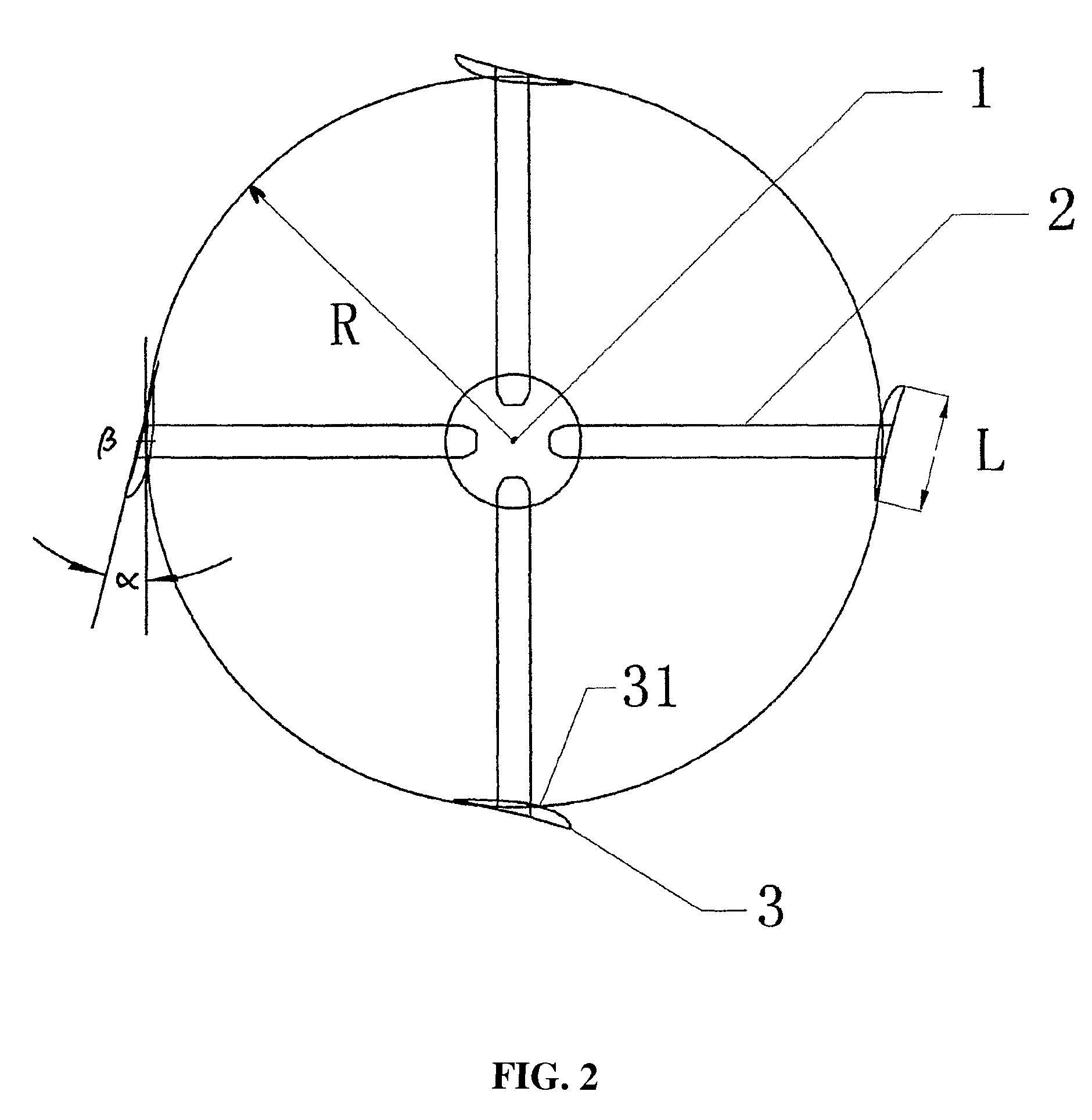
[0034]With reference to FIGS. 1 and 2, the vertical axis wind turbine of this invention comprises vertical axis 1, support arms 21 and 22 connected to the vertical axis 1, a wind rotor consisting of a plurality of blades mounted to support arm 2, blades 3 connected to axis sleeve 5 through support arms 21 and 22, and a flange 4. An aerofoil of the blade 3 is a dissymmetrical aerofoil with camber. The blade is mounted such that its convex surface 31 faces vertical axis 1.

[0035]The radius of the wind rotor was 0.68 m. The cumber-airfoil blade Goe63 was mounted in such a way that its convex surface faces vertical axis. The blade rotating angle was between 0 and 10 degrees. The number of blades was 5. The wind speed was 10 m / s. The rotating speeds and output power of the wind rotor was by CFW under different radius / chord ratios.

[0036]With reference to FIG. 3, when the radius / chord ratio of a wind rotor a...

example 2

Rotating Speed and Power by Computer Simulative Calculation under Different Blade Rotating Angles.

[0041]The radius of the wind rotor was 0.68 m. The cumber-airfoil blade Goe63 was mounted such that its convex surface faced the vertical axis. The number of blades was 5. The wind speed was 10 m / s. Then the rotating speeds and output power of the wind rotor were calculated by CFW under different blade rotating angles.

[0042]With reference to FIG. 4, when the blade rotating angle is between 0 and 10 degrees, the wind rotor can obtain a relatively large power. A better power is obtained when the blade rotating angle is between 2 and 8 degrees. However, a progressively smaller blade rotating angle will affect the start-up of the rotor.

[0043]When the wind rotor is static, the blade is resistance-free. A blade can get a large moment of torque to easily start the wind rotor with a large blade rotating angle; while a blade can get a small moment of torque and have difficulty in starting the wi...

example 3

Output Power of the Wind Rotor by Computer Simulative Calculation with Different Number of Blades

[0045]The radius of the wind rotor was 0.68 m. The cumber-airfoil blade Goe63 was mounted such that its convex surface faces vertical axis. The wind speed was 10 m / s. Then, a curve for the rotating speeds and output power of the wind rotor under different blade rotating angles was calculated.

[0046]As shown in FIG. 5, by comparing the wind rotor respectively consisting of 3, 5, 6 blades, when the chord length of the blade is constant, as the number of blades increases, the distance between adjacent blades is shortened, then the vortex produced at the rear edge of the previous blade increases the aerodynamic resistance on the next blade, thus the moment of the wind rotor decreases. However, if the number of blades is too small, the moment acting on the wind rotor will decrease accordingly. It was determined experimentally that a wind rotor consisting of 5 blades would produce a maximum out...


PUM

PropertyMeasurementUnit
angleaaaaaaaaaa
angleaaaaaaaaaa
blade rotating angleaaaaaaaaaa

Abstract

A vertical axis wind turbine comprising: a plurality of support arms (2) connected with a vertical axis (1), a wind rotor comprising a plurality of blades (3) connected to the blade support arms (2), the wind rotor having a rotation radius and the blades (3) having a chord length; wherein an airfoil of the blade is an asymmetrical camber airfoil, the convex surface (31) of the blade (3) faces vertical axis (1), and a ratio of the rotation radius of the wind rotor (R) to the chord length of the blade (L) is between about 1.8 and about 4.

Description

CROSS-REFERENCE TO RELATED APPLICATIONS[0001]This application is a continuation-in-part of International Patent Application No. PCT / CN2007 / 001983 with an international filing date of Jun. 25, 2007, designating the United States, now pending, is a continuation-in-part of U.S. application Ser. No. 12 / 234,784 filed on Sep. 22, 2008, which is a continuation-in-part of International Patent Application No. PCT / CN2007 / 000958 with an international filing date of Mar. 26, 2007, designating the United States, now pending. This application claims priority benefits of Chinese Patent Application No. 200610028267.7 filed Jun. 28, 2006 and of Chinese Patent Application No. 200610025202.7 filed Mar. 29, 2006. The contents of all of the aforementioned specifications, including any intervening amendments thereto, are incorporated herein by reference.BACKGROUND OF THE INVENTION[0002]1. Field of the Invention[0003]This invention relates to a vertical axis wind turbine, and particularly to an arrangemen...

Claims


Application Information

Patent Timeline
Patent Type & Authority Patents(United States)
IPC IPC(8): B21K25/00
CPCF03D3/064F05B2240/301Y10T29/49321Y10T29/49316Y02E10/74
Inventor YAN, QIANG
Owner YAN QIANG
Why Eureka
Try Eureka