

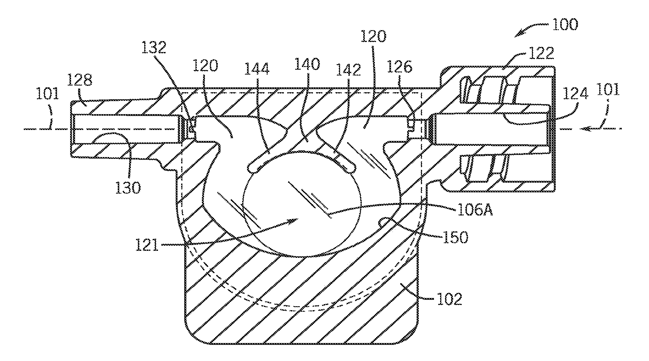
Off-axis blood chamber
a blood chamber and off-axis technology, applied in the field of single-use blood chambers, can solve the problems of continuous mixing and homogeneity in the blood being measured, and achieve the effects of facilitating emission and detection, causing continuous mixing and homogeneity in the blood being measured, and efficient and complete blood flow
- Summary
- Abstract
- Description
- Claims
- Application Information
AI Technical Summary
Benefits of technology
Problems solved by technology
Method used
Image

Examples
Embodiment Construction
Prior Art
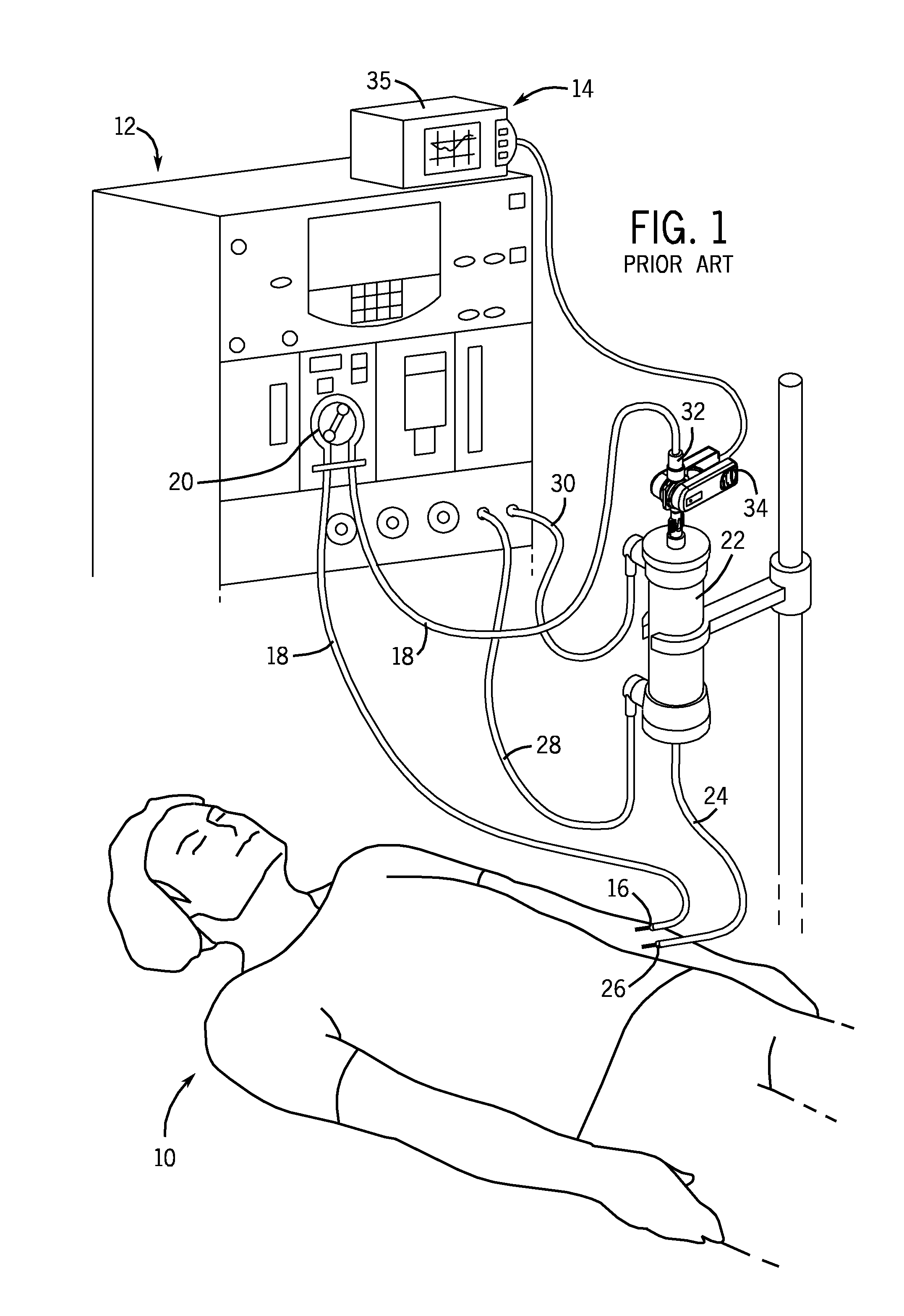
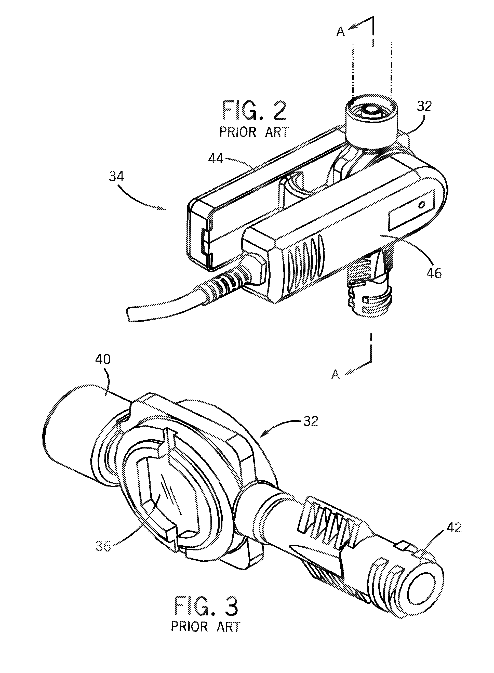
[0025]FIG. 1 illustrates a patient 10 undergoing hemodialysis treatment with a conventional hemodialysis system 12, and also illustrates a non-invasive, optical blood monitor 14. A typical hemodialysis clinic will have several hemodialysis systems 12 for treating patients.
[0026]An input needle or catheter 16 is inserted into an access site of the patient 10, such as shunt in the arm, and is connected to extracorporeal tubing 18 that leads to a peristaltic pump 20 and then to a dialyzer or blood filter 22. The dialyzer 22 removes toxins and excess fluid from the patient's blood. The dialysized blood is returned from the dialyzer 22 to the patient through extracorporeal tubing 24 and a return needle or catheter 26. The extracorporeal blood flow normally receives a heparin drip to prevent clotting although that is not shown in FIG. 1. Excess fluids and toxins are removed by clean dialysate liquid which is supplied to the dialyzer 22 via tube 28 and removed for disposal via tub...
PUM
 Abstract
Description
Claims
Application Information