Charge/discharge control apparatus

a control apparatus and discharge device technology, applied in the direction of electric devices, process and machine control, data processing applications, etc., can solve the problems of future increase in the number of installations using storage batteries, timer control technique limitation, and the inability to optimize the whole power installation, so as to reduce the flat electric power rate

Active Publication Date: 2012-12-11
HITACHI LTD
View PDF13 Cites 30 Cited by
  • Summary
  • Abstract
  • Description
  • Claims
  • Application Information

AI Technical Summary

Benefits of technology

[0019]Those means enables to draw up a socially-suitable charge / discharge plan within a range not giving inconvenience to a user, while based on the charge / discharge reward information. For example, if a user is scheduled to drive an electric vehicle at a given time on the following day, a charging plan can be created within a range not negatively affecting the time of departure on the following day with at least a partial contribution to the environment.
[0021]Even such a partial contribution has an effect of encouraging a user to willingly participate in the program. The charge / discharge control apparatus can obtain a degree of contribution made by each user, from the external facility because the charge / discharge control apparatus has the means for monitoring or reporting whether or not a charge / discharge has been actually conducted. The charge / discharge control apparatus can reduce a flat electric power rate regarding a power usage amount used for a charging and provide various merits to the users.

Problems solved by technology

Of the conventional techniques described above, the technique using a timer control has, however, a problem of having a difficulty in dealing with a future increase in the number of installations using storage batteries.
The conventional technique using a timer control has a limitation in that optimization of the whole power installations is attempted by changing timer-controlled parameters via off-line operations on a case-by-case basis.
In reality, however, a user does not always conduct a charge / discharge action as originally planned because of an accidental event or the like.
It is therefore difficult that all of the users send all of their charging requests to the external facility without fail.
Any of the related arts described above have a difficulty in offering a social program for leading a customer to a desired charge / discharge action.
Otherwise, such a charging gives inconvenience to the user.

Method used


Image

  • Charge/discharge control apparatus
  • Charge/discharge control apparatus
  • Charge/discharge control apparatus

Examples


first embodiment

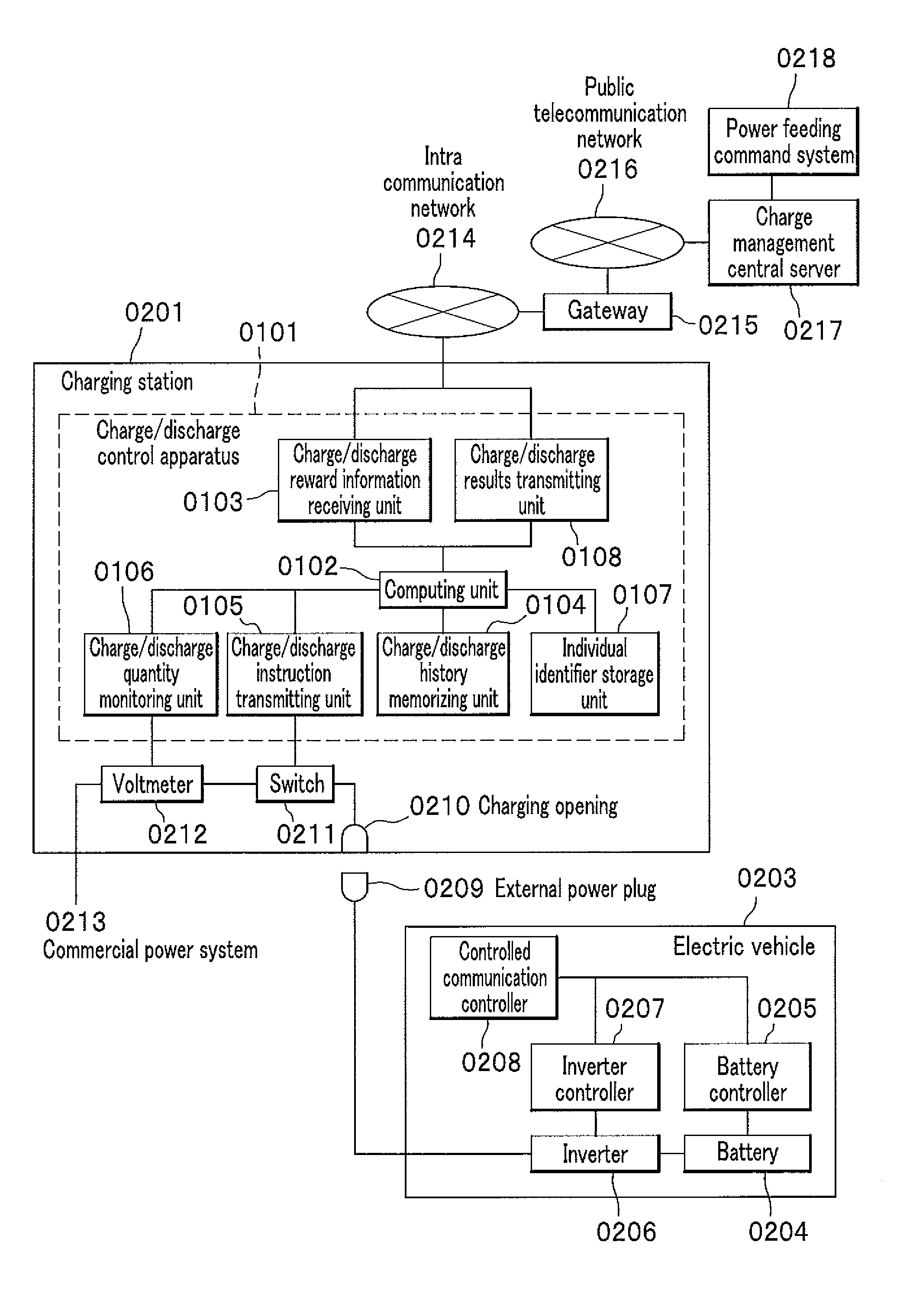
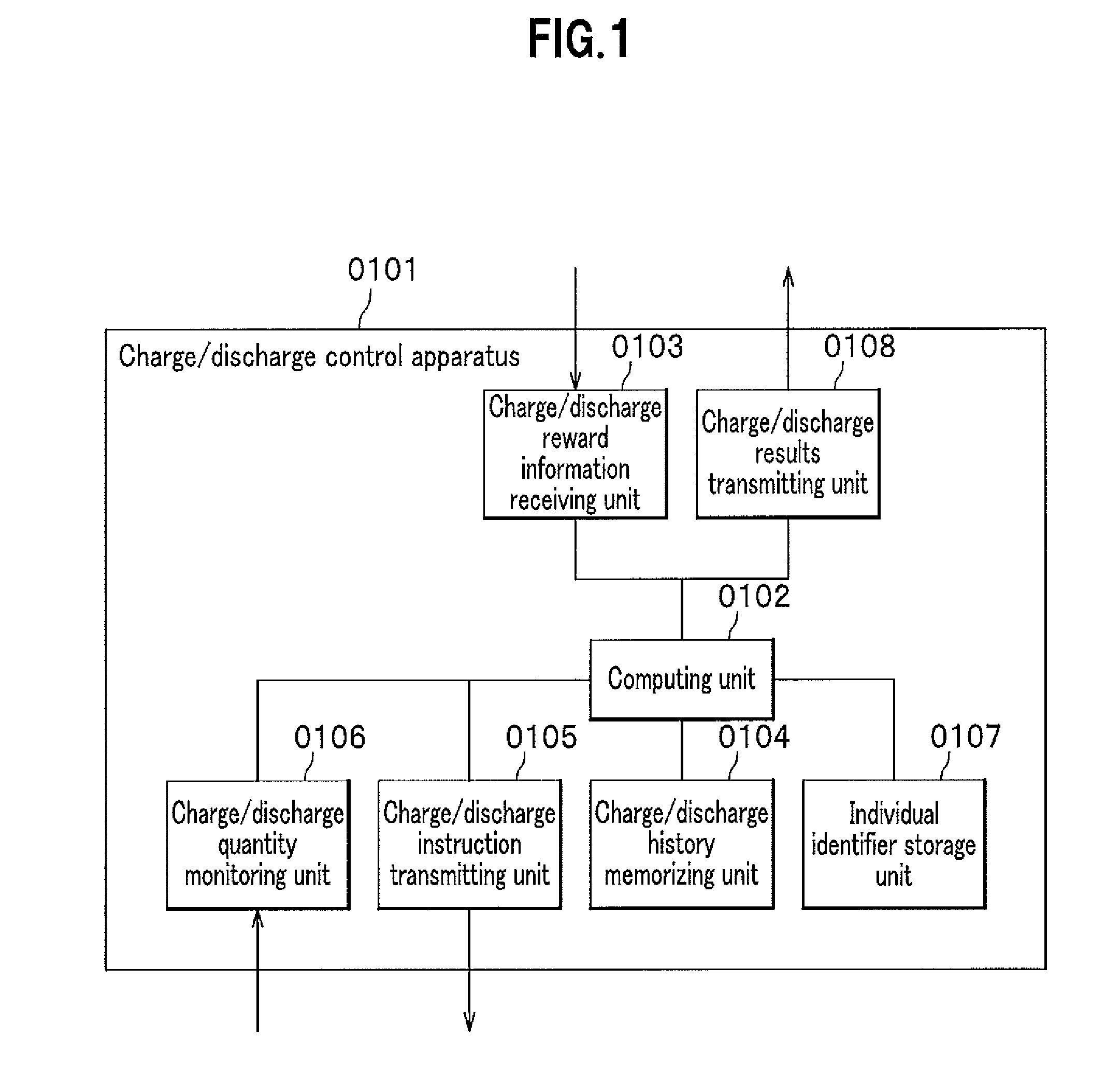
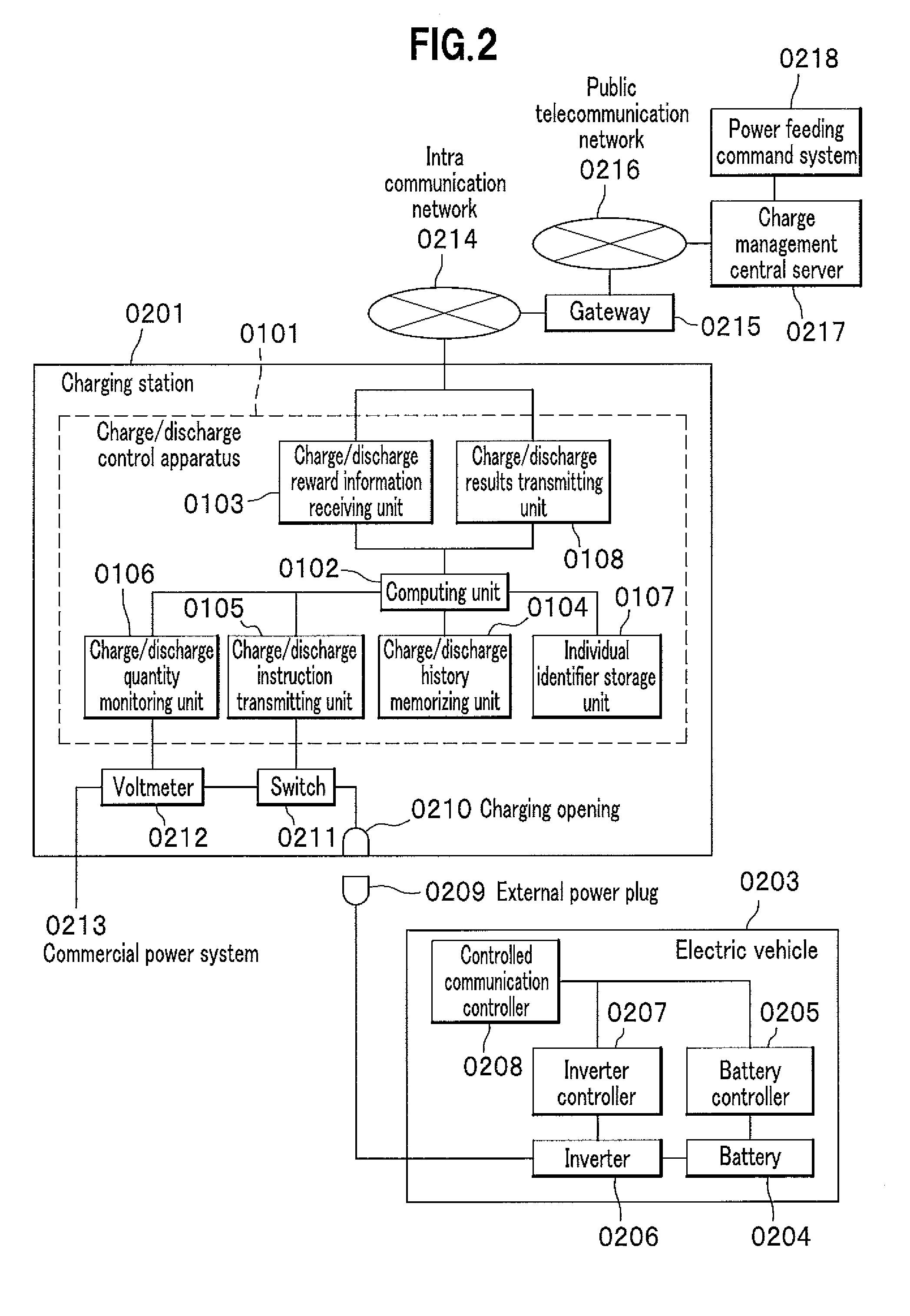
[0041]FIG. 1 shows a functional configuration of a charge / discharge control apparatus according to a A charge / discharge control apparatus 0101 includes a computing unit 0102 and various input and output units for coordinating with an external facility. A charge / discharge reward information receiving unit 0103 receives charge / discharge reward information which quantitatively represents a degree of contribution to society made by a charge / discharge action (a degree of positive or negative influence on society) for each time zone, from a computer as the external facility. A memory unit not shown of the charge / discharge control apparatus 0101 memorizes the received charge / discharge reward information.

[0042]The computing unit 0102 estimates an estimated usage start time and an estimated used power quantity of a power installation targeted for use, based on the charge / discharge reward information as well as history information stored in a charge / discharge history memorizing unit 0104 and...

third embodiment

[0090]A car navigation system 1601 has an interface which can communicate information with the respective units of the charge / discharge control apparatus 0101. The car navigation system 1601 coordinates with the charge management central server 0217 using an information communication function of the public telecommunication network 0216 connected to the public line communicating unit 1407. The car navigation system 1601 (which may also be referred to as a positioning device) also has a positioning function. Similarly to the third embodiment, the function makes it possible to encourage a charge / discharge action according to a condition of a power distribution installation.

[0091]A drive plan information receiving unit 1602 grasps a drive plan prepared by the car navigation system 1601. The car navigation system 1601 sets a start point, a destination point, and a route for connecting the two points in advance according to well-known functions thereof. The car navigation system 1601 cre...


PUM

PropertyMeasurementUnit
power quantityaaaaaaaaaa
distanceaaaaaaaaaa
total drive distanceaaaaaaaaaa

Abstract

A charge / discharge control apparatus includes: a charge / discharge reward information receiving unit for receiving charge / discharge reward information representing a reward given to a charge / discharge action of a customer and a restriction in conducting a charging / discharging from a charge management central server; a computing unit for creating a charge / discharge plan including a total charging quantity in a time zone and an estimated use start time of an electric vehicle such that a reward is maximized, based on the charge / discharge reward information; a charge / discharge instruction transmitting unit for instructing the electric vehicle to start or finish a charging / discharging according to the charge / discharge plan; a charge / discharge quantity monitoring unit for monitoring the charging / discharging; and a charge / discharge results transmitting unit for transmitting results of monitored charging / discharging including contents of the conducted charging / discharging and individual identification information for identifying itself, to a charge management central server.

Description

CROSS REFERENCE TO RELATED APPLICATIONS[0001]This application claims the benefit of Japanese Patent Application No. 2008-246550 filed on Sep. 25, 2008, the disclosure of which is incorporated herein by reference.BACKGROUND OF THE INVENTION[0002]1. Field of the Invention[0003]The present invention relates to a technique of indirectly controlling a start time or an end time of a charge / discharge and a quantity of the charge / discharge so as to achieve a charge / discharge plan of an electric storage installation using a secondary battery connected to a wide-area power system, in particular, so as to improve an energy consumption performance and a social environmental performance as a whole power system in terms of a number of storage batteries freely connected in parallel and disconnected by end users.[0004]2. Description of the Related Art[0005]Electric power installations using storage batteries, that is, electric storage installations have been recently expected to come into wide use ...

Claims


Application Information

Patent Timeline
Patent Type & Authority Patents(United States)
IPC IPC(8): H02J7/00B60L3/00B60L11/18G06Q50/00G06Q50/06H01M10/44H02J3/00H02J3/14H02J3/32H02J3/38H02J7/02H02J7/34
CPCB60L3/12B60L11/1838B60L11/184B60L11/1842B60L11/1846B60L11/1848B60L11/1862G06Q30/0207G06Q50/06B60L11/1816Y02E60/721B60L2230/16B60L2260/56H02J3/32Y02T10/7005Y02T10/7044Y02T10/705Y02T10/7088Y02T90/121Y02T90/128Y02T90/14Y02T90/163Y02T90/169Y04S10/126Y04S30/14B60L53/14B60L53/60B60L53/64B60L55/00B60L53/65B60L53/665B60L53/305H02J2310/48H02J3/322Y02E60/00Y02T10/70Y02T10/7072Y02T90/12Y02T90/167Y02T90/16
Inventor SATO, YASUOMATSUZAKI, TAKAOWATANABE, MASAHIROTOMITA, YASUSHI
Owner HITACHI LTD
Why Eureka
Try Eureka