
Device and method for quantification of gases in plumes by remote sensing

a technology of remote sensing and devices, applied in measurement devices, instruments, color/spectral properties measurements, etc., can solve the problems of large amount of labor and skill, large amount of system cost, and large contribution of vehicle emissions to air pollution

Active Publication Date: 2012-12-11
HAGER ENVIRONMENTAL & ATMOSPHERIC TECH
View PDF19 Cites 15 Cited by
  • Summary
  • Abstract
  • Description
  • Claims
  • Application Information

AI Technical Summary

Benefits of technology

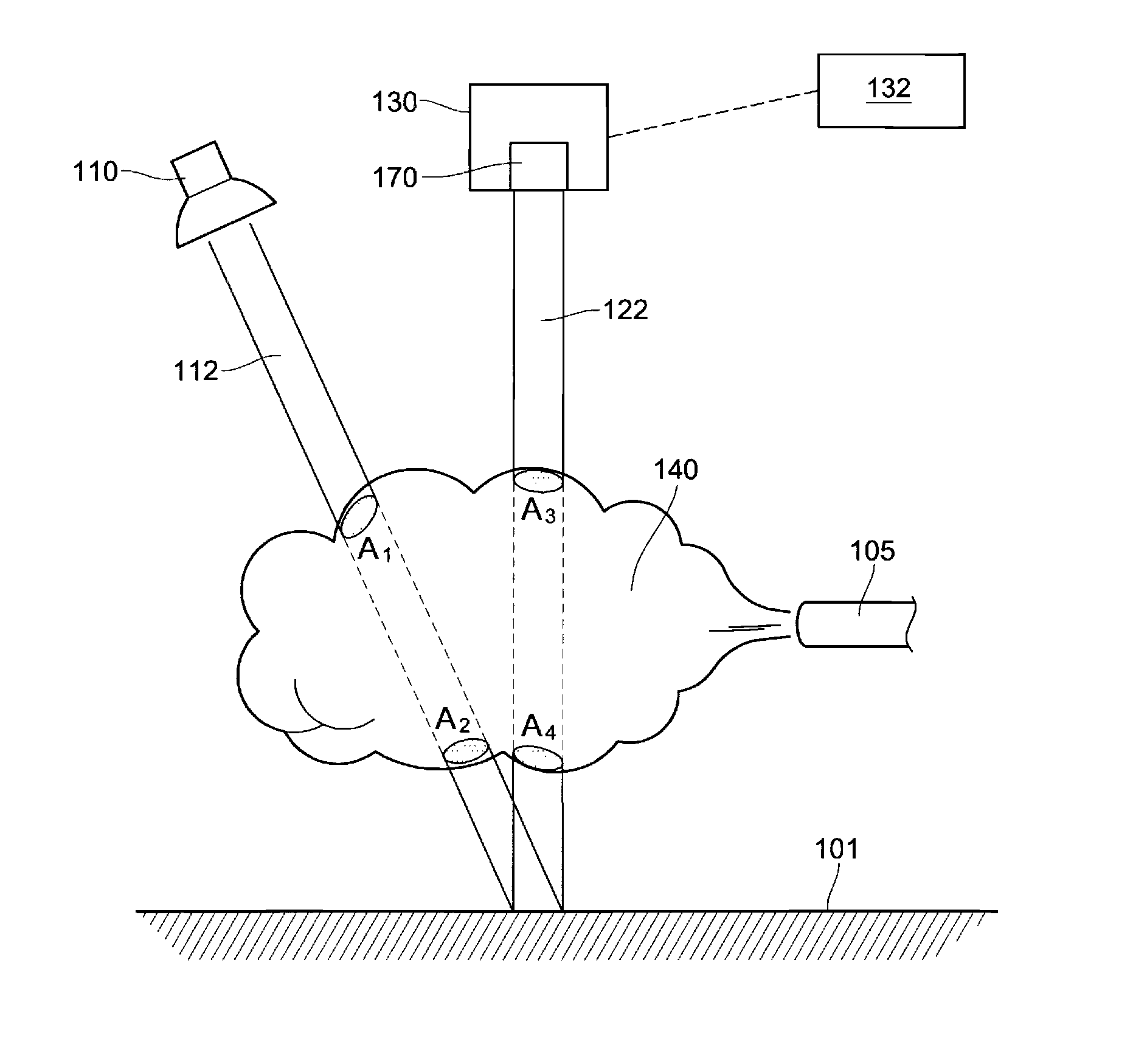
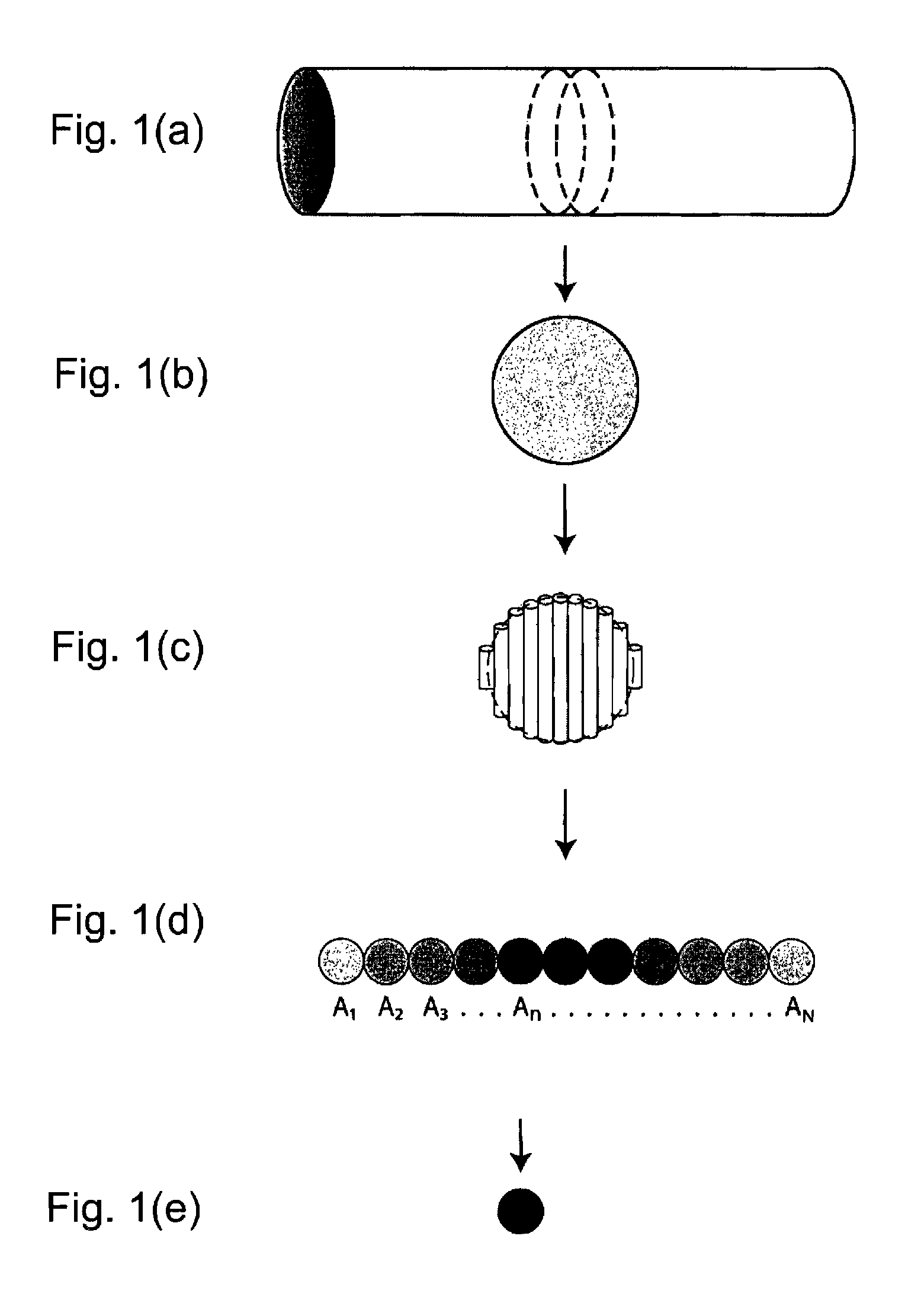
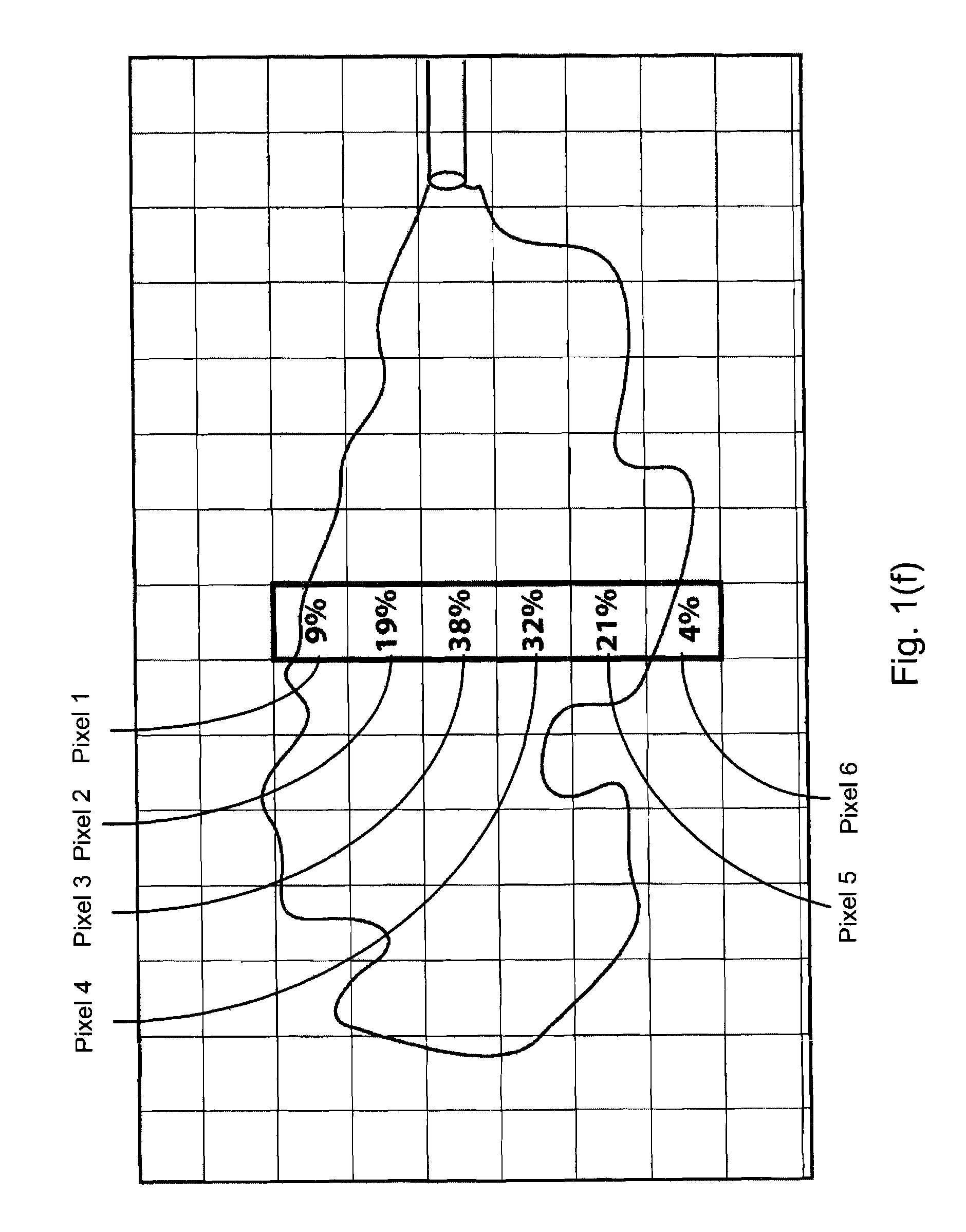
"The present invention is a device that uses infrared and / or ultraviolet images to measure the amount of ingredients in a plume. The device comprises a source for emitting a beam of light, a detector for capturing images of the plume, and a processor for processing the captured images. The device can measure the optical mass of each pixel in the plume by analyzing the absorption rate of light and the projected area of the pixel. The device can be used to measure the amount of specific gases in the plume by using filters that absorb the gases. The device can be modulated to measure hot exhaust or the transmission of the light through the plume. The detector can be an infrared or ultraviolet camera with filters or a detector array. The invention provides a non-invasive and accurate method for measuring the composition of exhaust plumes."

Problems solved by technology

It is known that vehicle emissions are a major contributor to air pollution.
Generally, these systems can be very expensive, and their operation can require a vast amount of labor and skill.
Although such measurements provide general baseline information regarding a vehicle's emissions and state of repair, it is not necessarily representative of “real world” driving conditions.
However, for such remote emission sensing systems, the source, detector and reflectors are set up on both sides of the road, and much care needs to be taken during their installation and maintenance.
Additionally, such a system is difficult to operate with more than one lane of traffic particularly when more than one vehicle passes through the detector simultaneously.
Thus, on a single lane road, such as entrance and exit ramps, the existing remote sensing systems are not able to detect more than one exhaust plume at a time.
Ultimately, the main drawback to current remote emission sensing is that since it only measures a portion of an exhaust plume it can only determine a plume's constituent gases and their relative concentrations.
While such results can indicate if a vehicle is in need of repair, existing systems are not able to measure absolute amounts of emission components.
Unfortunately, the complexity of this method is unnecessary and cost prohibitive.
Therefore, a heretofore unaddressed need exists in the art to address the aforementioned deficiencies and inadequacies.

Method used


Image

  • Device and method for quantification of gases in plumes by remote sensing
  • Device and method for quantification of gases in plumes by remote sensing
  • Device and method for quantification of gases in plumes by remote sensing

Examples


Embodiment Construction

[0050]The present invention is more particularly described in the following examples that are intended as illustrative only since numerous modifications and variations therein will be apparent to those skilled in the art. Various embodiments of the invention are now described in detail. Referring to the drawings, like numbers indicate like components throughout the views. As used in the description herein and throughout the claims that follow, the meaning of “a”, “an”, and “the” includes plural reference unless the context clearly dictates otherwise. Also, as used in the description herein and throughout the claims that follow, the meaning of “in” includes “in” and “on” unless the context clearly dictates otherwise. Additionally, some terms used in this specification are more specifically defined below.

[0051]The terms used in this specification generally have their ordinary meanings in the art, within the context of the invention, and in the specific context where each term is used....


PUM

PropertyMeasurementUnit
average wavelengthaaaaaaaaaa
areaaaaaaaaaaa
optical massaaaaaaaaaa

Abstract

In one aspect, the present invention relates to a device quantifying absolute amounts of ingredients of a plume. In one embodiment, the device comprises a source for emitting a beam of light and transmitting the emitted light through the plume to a surface on which the transmitted light is scattered, a detector for acquiring an image of the exhaust plume, the acquired image containing information of absorption of the scattered light scattered from the surface, and a processor for processing the acquired image to determine an absolute amount of at least one of components of the exhaust plume.

Description

CROSS-REFERENCE TO RELATED PATENT APPLICATION[0001]This application is a continuation-in-part of U.S. patent application Ser. No. 12 / 493,634, filed Jun. 29, 2009, entitled “DEVICE FOR REMOTE SENSING OF VEHICLE EMISSION,” by J. Stewart Hager, which is incorporated herein in their entireties by reference.[0002]Some references, which may include patents, patent applications and various publications, are cited and discussed in the description of this invention. The citation and / or discussion of such references is provided merely to clarify the description of the present invention and is not an admission that any such reference is “prior art” to the invention described herein. All references cited and discussed in this specification are incorporated herein by reference in their entireties and to the same extent as if each reference were individually incorporated by reference.FIELD OF THE INVENTION[0003]The present invention generally relates to remote detection of emission, and more part...

Claims


Application Information

Patent Timeline
Patent Type & Authority Patents(United States)
IPC IPC(8): G01N21/00
CPCG01N21/33G01N21/3504G01N2021/1795G01N2021/399
Inventor HAGER, J. STEWART
Owner HAGER ENVIRONMENTAL & ATMOSPHERIC TECH
Learn More