
VSWR normalizing envelope modulator

a technology of amplification circuit and amplification envelope, applied in the direction of modulation, transmission monitoring, gain control, etc., can solve the problems of affecting the performance of the system, adding cost in the form of detection diodes or dual logarithmic amplifiers, and difficult circuit design problems, etc., to achieve the effect of reducing the cost of detection diodes or dual logarithmic amplifiers, and reducing the cost of reducing

Active Publication Date: 2012-12-11
APPLE INC
View PDF33 Cites 6 Cited by
  • Summary
  • Abstract
  • Description
  • Claims
  • Application Information

AI Technical Summary

Benefits of technology

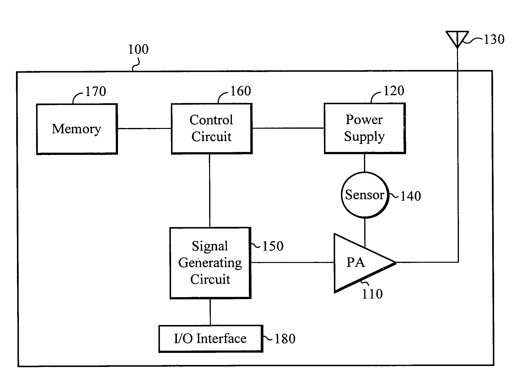
[0007]A relationship is established between measurable characteristics of the power input to a power amplifier and the output power level. A power circuit is configured to measure the input supply current to the pow

Problems solved by technology

System requirements that demand the leveling of this output power as the load impedance changes present difficult circuit design problems which are particularly troublesome in a cost sensitive environment.
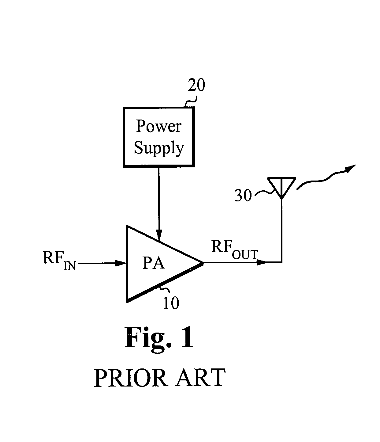
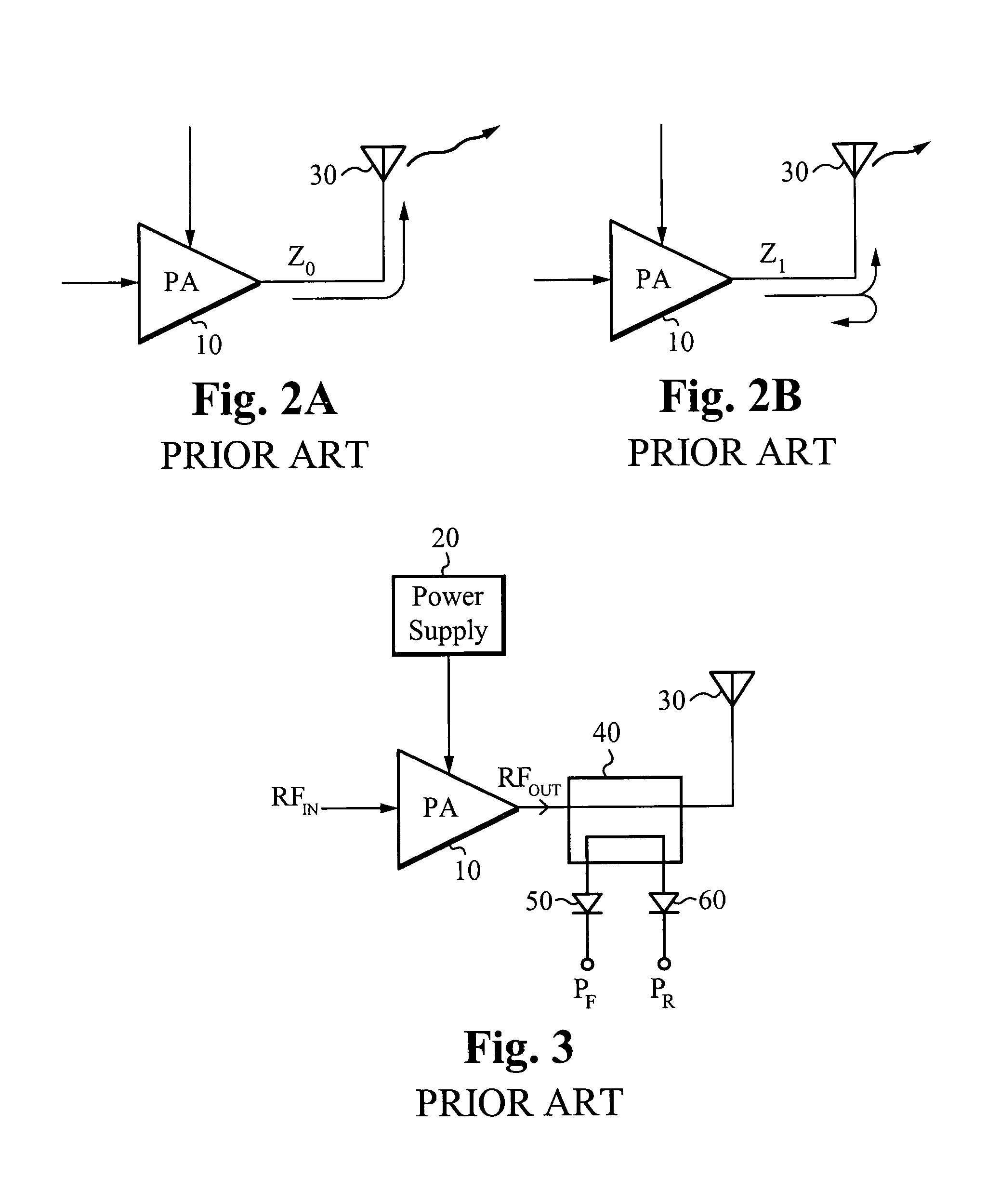
Measuring the VSWR directly at the output of the power amplifier, using well-known radio frequency (RF) VSWR measurement methods, adds cost in terms of a dual directional coupler, detection diodes or dual logarithmic amplifiers, and other overhead such as additional analog to digital conversion(s).
In many cases, such a mismatch can be quite substantial and will negatively impact the performance of the system. FIG. 2B illustrates a mismatched load impedance condition.
Additionally, the reflected power is potentially harmful to the power amplifier, leading to possible damage or destruction.
There are many problems associated with using a detection circuit, such as that of FIG. 3, at the output of the power amplifier.
There are many additional parts which adds complexity, size, and cost.
Further, the detection circuit results in some power loss, so that even under ideal conditions the output power is reduced leading to an overall drop in efficiency.
Also, use of a detection circuit requires additional logic circuitry necessary to perform the additional calculations.

Method used


Image

  • VSWR normalizing envelope modulator
  • VSWR normalizing envelope modulator
  • VSWR normalizing envelope modulator

Examples


Embodiment Construction

[0023]Embodiments of the present invention are directed to a power amplification circuit to provide a normalized output power signal under mismatched load impedance conditions. Those of ordinary skill in the art will realize that the following detailed description of the present invention is illustrative only and is not intended to be in any way limiting. Other embodiments of the present invention will readily suggest themselves to such skilled persons having the benefit of this disclosure.

[0024]Reference will now be made in detail to implementations of the present invention as illustrated in the accompanying drawings. The same reference indicators will be used throughout the drawings and the following detailed description to refer to the same or like parts. In the interest of clarity, not all of the routine features of the implementations described herein are shown and described. It will, of course, be appreciated that in the development of any such actual implementation, numerous ...


PUM


Abstract

A relationship is established between measurable characteristics of the DC power input to a power amplifier and the RF output power level. A power circuit is configured to measure the input supply current to the power amplifier and to utilize the relationship between the input supply current and the applied input supply voltage to the output power level, thereby normalizing the output power of an amplified communication signal.

Description

FIELD OF THE INVENTION[0001]The present invention relates to power amplification circuits, and more particularly, to a power amplification circuit configured to normalize an output power.BACKGROUND OF THE INVENTION[0002]The power delivered by a power amplifier to a load resistance depends on the voltage standing wave ratio (VSWR), that is, the change in the magnitude and phase of the reflection coefficient referenced to the designed load resistance, also referred to as the nominal load resistance or the nominal load impedance. System requirements that demand the leveling of this output power as the load impedance changes present difficult circuit design problems which are particularly troublesome in a cost sensitive environment. Measuring the VSWR directly at the output of the power amplifier, using well-known radio frequency (RF) VSWR measurement methods, adds cost in terms of a dual directional coupler, detection diodes or dual logarithmic amplifiers, and other overhead such as ad...

Claims


Application Information

Patent Timeline
IPC IPC(8): H01Q11/12
CPCH03G3/007H03F1/08H03F3/24
Inventor MCCUNE, EARL W.BOOTH, RICHARD W. D.
Owner APPLE INC
Learn More