Latch device for vehicle seat

a technology for vehicle seats and latches, which is applied in the direction of roofs, movable seats, couplings, etc., can solve the problems of generating noise by latches and ratchets, loose latches, and seat looseness, so as to prevent loosening of latches and avoid noise generation, the effect of generating nois

Inactive Publication Date: 2012-12-18
TS TECH CO LTD
View PDF6 Cites 23 Cited by
  • Summary
  • Abstract
  • Description
  • Claims
  • Application Information

AI Technical Summary

Benefits of technology

[0005]In the known art, the striker is pressed by the rubber damper, and functions to eliminate loosening and to force out (the striker) when unlatching, and therefore when a load more than a flexible rigidity of the damper is applied, the striker deflects the damper and moves, thereby causing looseness of the latch assembly and instability of the seat.
[0006]When the load is decreased, the damper is restored elastically, and the striker and the latch return to the original position, thereby generating noise by the latch and ratchet hitting against each other.
[0008]It is hence an object of the invention to provide a latch device of a vehicle seat capable of preventing loosening of a latch assembly, instability of the seat, and generation of noise when the striker and the latch return to the original position.

Problems solved by technology

In the known art, the striker is pressed by the rubber damper, and functions to eliminate loosening and to force out (the striker) when unlatching, and therefore when a load more than a flexible rigidity of the damper is applied, the striker deflects the damper and moves, thereby causing looseness of the latch assembly and instability of the seat.
When the load is decreased, the damper is restored elastically, and the striker and the latch return to the original position, thereby generating noise by the latch and ratchet hitting against each other.
On the other hand, the configuration in which the striker is in contact with the damper and is arrested not to move further inward, is difficult to realize because a slight gap may be formed between the engaging groove of the latch and the striker due to a manufacturing or assembling error.

Method used


Image

  • Latch device for vehicle seat
  • Latch device for vehicle seat
  • Latch device for vehicle seat

Examples


Embodiment Construction

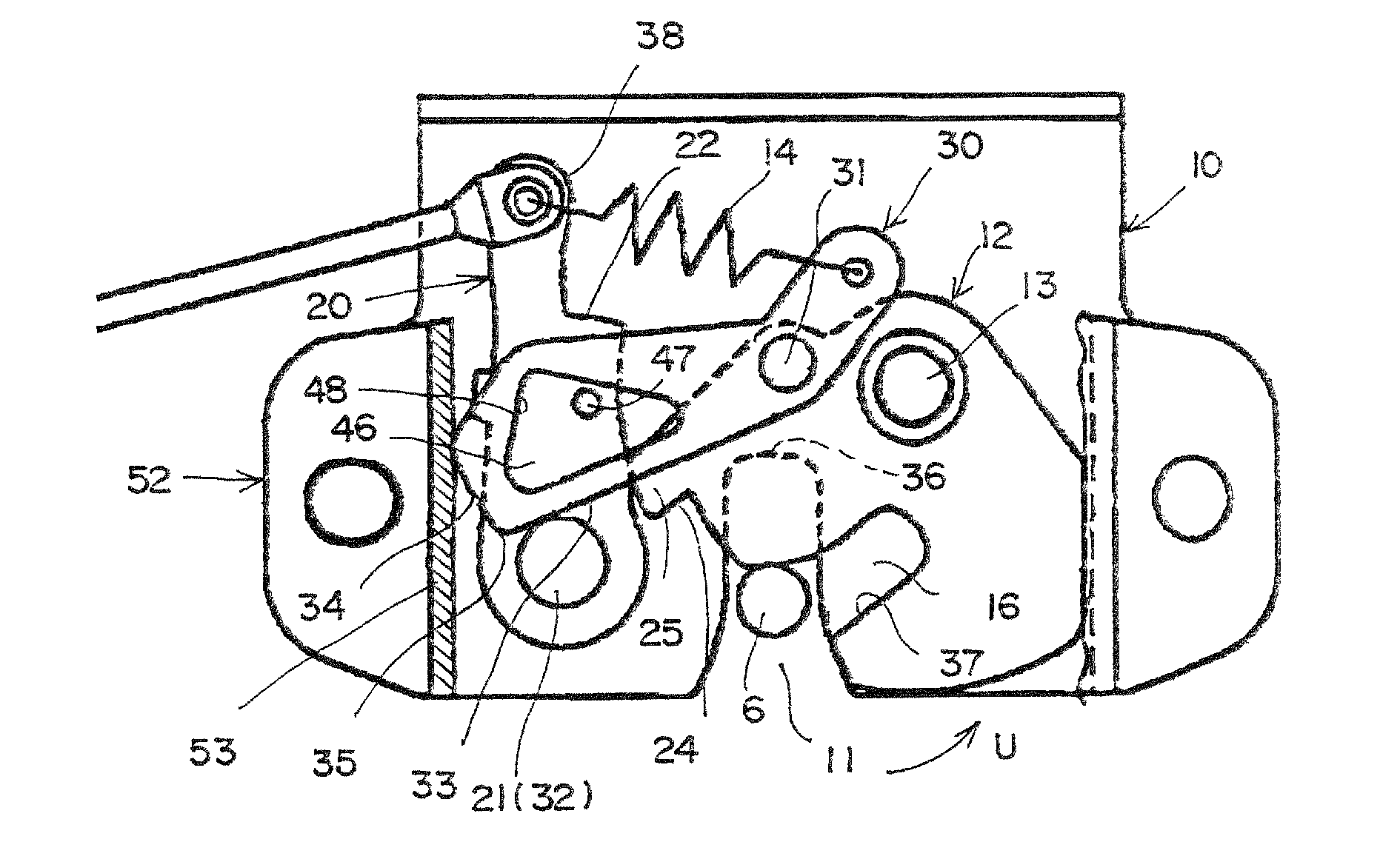
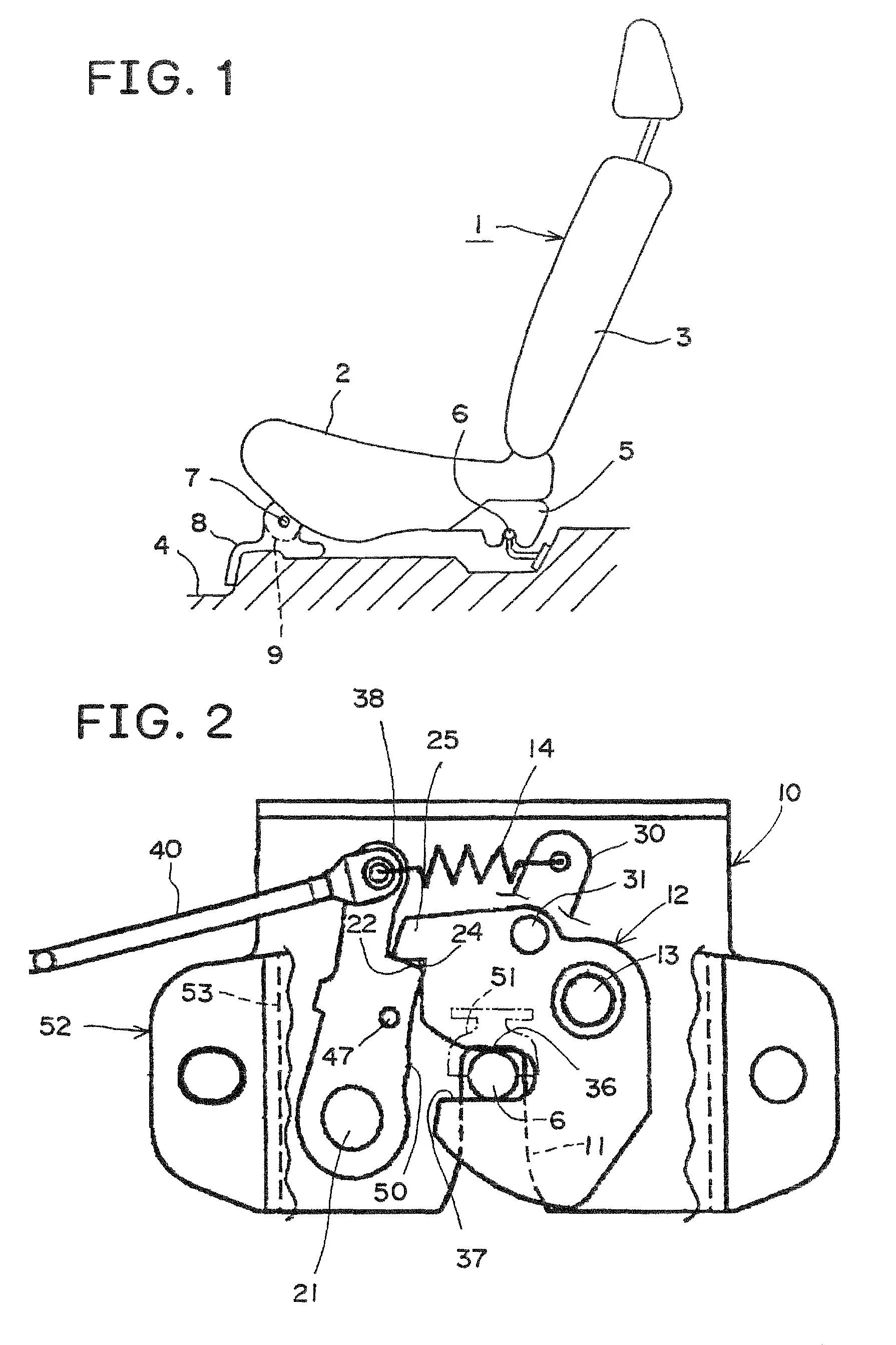
[0020]An example of the invention will be described with reference to the drawings. A vehicle seat 1 has a seat bottom 2 and a backrest 3. The front side of the vehicle seat 1 shown in FIG. 1 is coupled to an engaging part 8 of a car body 4 and an engaging part 9 of the seat 1 by means of a horizontal mounting shaft 7, and the rear side of the vehicle seat 1 is coupled to a striker 6 and a latch assembly 5. By clearing the engagement between the striker 6 and the latch assembly 5, the vehicle seat 1 is released to be rotatable between the position of use and the moving position to and from the horizontal shaft 7. Further, the front side of the vehicle seat 1 may be also coupled to the car body by means of the striker 6 and the latch assembly 5, and the rear side of the vehicle seat 1 may be coupled by means of the horizontal shaft 7.

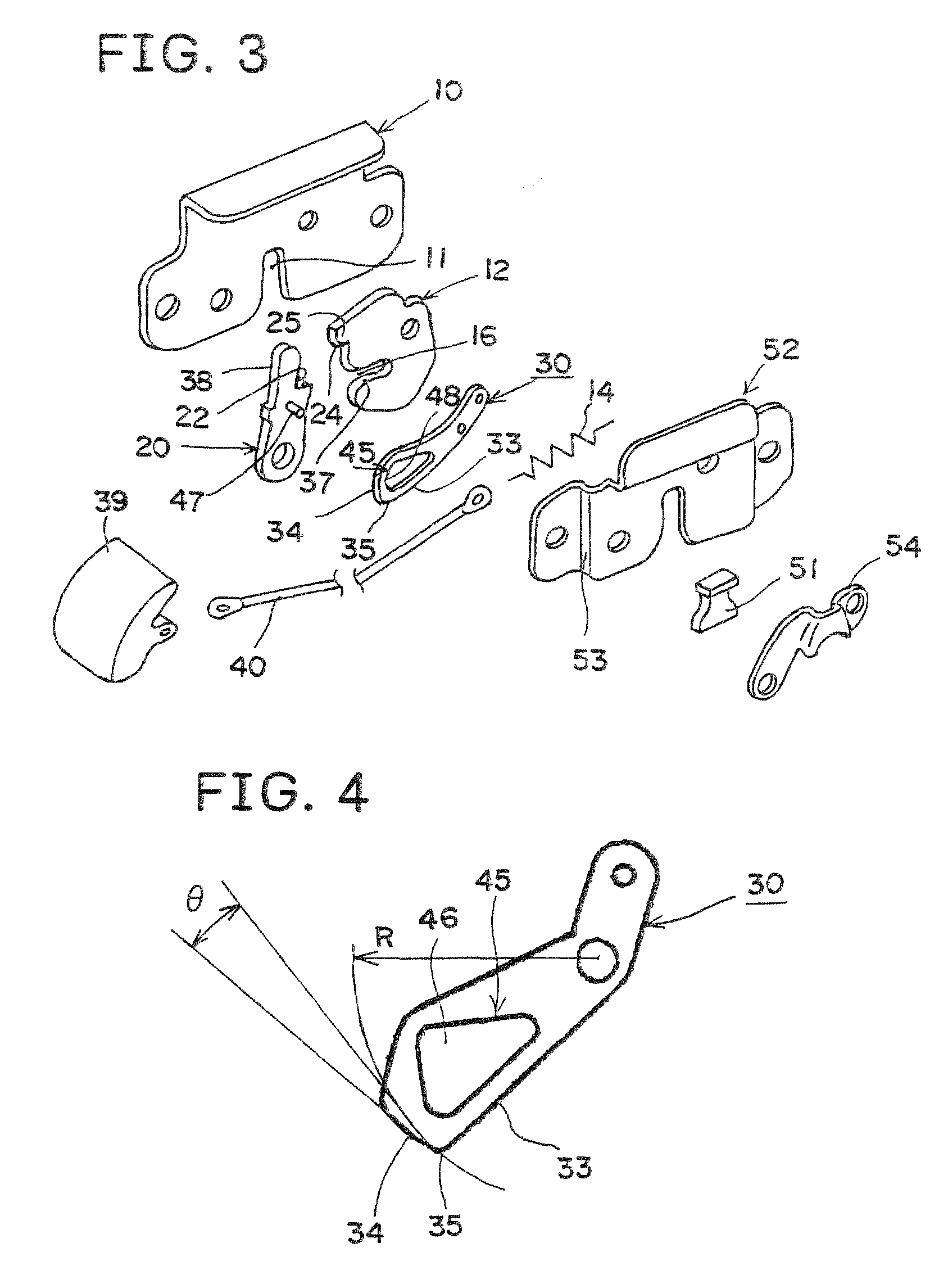
[0021]The present invention also relates to the configuration of the latch assembly 5, and the configuration of the coupling portion not using the latch...


PUM


Abstract

A latch assembly 5 includes a base plate 10 having a striker groove 11, a latch 12 provided in the base plate 10 and having a striker engaging groove 16, and a ratchet 20 for regulating rotation of the latch 12 in unlatch direction. A looseness eliminating lever 30 is attached to the latch 12 by means of a pin 31 moving around a latch shaft 13, one end of the looseness eliminating lever 30 is provided with a latch holding face 34 and an unlatch face 33 to contact with a post 32 provided at a specified position, the other end of the lever 30 is provided with a spring 14 for biasing the guide face 34 or the sliding face 33 to be always in contact with the post 32, and an apex 35 as a dead center is formed between the guide face 34 and the sliding face 33. The guide face 34 is formed in an arc-shaped inclined surface so as to be remoter from the pin 31 from a start end to a terminal end.

Description

TECHNICAL FIELD[0001]The present invention relates to a latch device for fixing, to a car body, a vehicle seat which is detachably mounted on a car body or is rotatably mounted on a car body.BACKGROUND ART[0002]Conventionally, a latch assembly for engaging and holding a striker by means of a latch and a ratchet was formed in a known configuration in which a rubber damper is provided at the inner side of a striker groove for receiving a striker, and the striker is engaged and held between the rubber damper and the inner circumference of the striker engaging groove of the latch (see, for example, patent documents 1 and 2).[0003]Patent document 1: Japanese UM Publication No. 6-7970[0004]Patent document 2: Japanese UM Laid-Open No. 58-27460DISCLOSURE OF THE INVENTION[0005]In the known art, the striker is pressed by the rubber damper, and functions to eliminate loosening and to force out (the striker) when unlatching, and therefore when a load more than a flexible rigidity of the damper ...

Claims


Application Information

Patent Timeline
Patent Type & Authority Patents(United States)
IPC IPC(8): B60N2/02
CPCB60N2/01583E05C3/24B60N2205/20Y10T403/608Y10T403/595Y10T403/599Y10T403/593
Inventor OMORI, MISAO
Owner TS TECH CO LTD
Why Eureka
Try Eureka