Feedback control circuit and power converting circuit

a control circuit and power conversion technology, applied in the direction of electrical equipment, instruments, light sources, etc., can solve the problems of reducing increasing so as to reduce the time and the amplitude of the oscillation of the error amplifying signal, reduce the stability of the circuit, and increase the probability of the circuit being burnt down

Active Publication Date: 2012-12-18
GREEN SOLUTION TECH CO LTD
View PDF3 Cites 6 Cited by
  • Summary
  • Abstract
  • Description
  • Claims
  • Application Information

AI Technical Summary

Benefits of technology

[0011]In the foregoing related art, the serious overshoot phenomenon due to the error compensation of feedback control reduces the stability of the circuit and increases the probability of the circuit being burnt down. Accordingly, an exemplary embodiment of the invention provides a set of an initial value of an error amplifying signal in the feedback control circuit for feedback control, so as to reduce the time and the amplitude of oscillation of the error amplifying signal. Accordingly, a feedback control circuit and a power converting circuit provided in an exemplary embodiment of the invention not only reduce the degree and the time of overshoot but also provide accurate and stable feedback control.

Problems solved by technology

In the foregoing related art, the serious overshoot phenomenon due to the error compensation of feedback control reduces the stability of the circuit and increases the probability of the circuit being burnt down.

Method used


Image

  • Feedback control circuit and power converting circuit
  • Feedback control circuit and power converting circuit
  • Feedback control circuit and power converting circuit

Examples


first embodiment

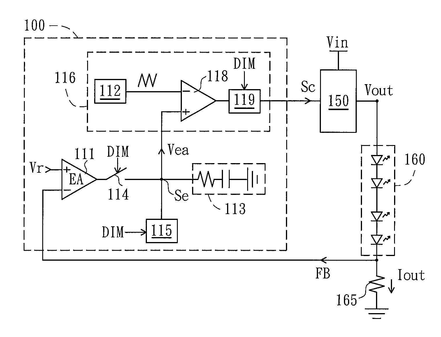
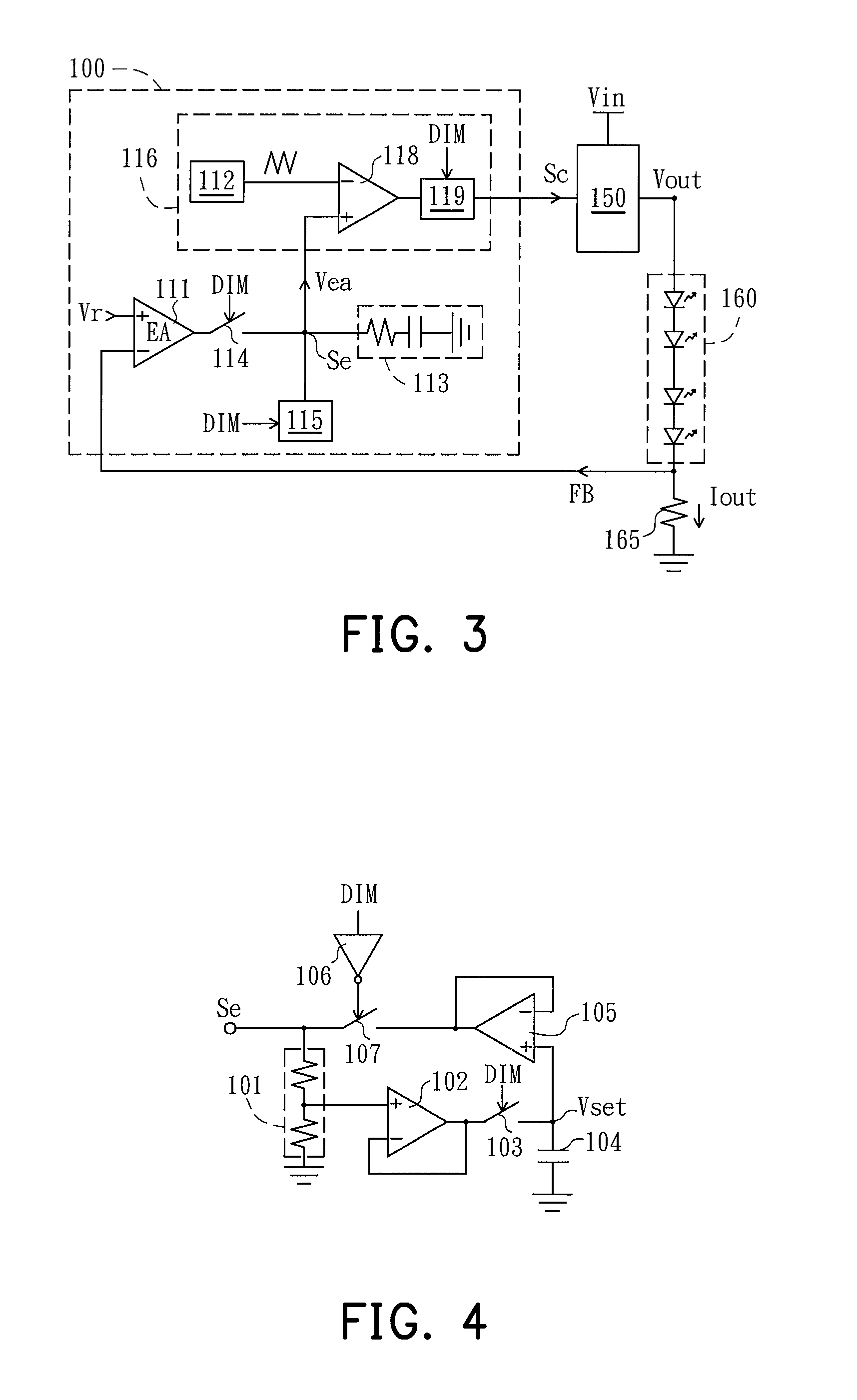
[0023]FIG. 3 is a schematic view of a power converting circuit according to the invention. Referring to FIG. 3, the power converting circuit includes a controller 100 and a converting circuit 150 to drive an LED module 160. The controller 100 receives a feedback signal FB and performs feedback control to generate a control signal Sc to control the converting circuit 150. The input end of the converting circuit 150 is coupled to an input voltage source Vin, and the output end thereof is coupled to the LED module 160. The converting circuit 150 adjusts the value of the electric power from the input voltage source Vin according to the control signal Sc and converts it into a suitable output voltage Vout to drive the LED module, such that an output current Iout flowing through the LED module is stabilized at a predetermined current value. The output current Iout also flows through a current detecting resistor 165 to generate the current feedback signal FB representing the amount of the ...

second embodiment

[0030]FIG. 6 is a schematic view of a power converting circuit according to the invention. Referring to FIG. 6, compared with that of the embodiment of FIG. 3, the power converting circuit further includes a driving switch 170 coupled to the LED module 160 in the present embodiment. FIG. 7 illustrates signal waveforms of the power converting circuit shown in FIG. 7 during dimming process. Referring to FIG. 6 and FIG. 7, when the state of the dimming signal DIM represents “ON”, the driving switch 170 is conducted, the operation of the power converting circuit is the same as that of the circuit shown in FIG. 3. When the state of the dimming signal DIM represents “OFF”, the driving switch 170 is cut off, such that the output current Iout can not flow to the ground through the current detecting resistor 165. That is, the path of which the converting circuit 150 provides the electric power to the LED module 160 is cut off. Accordingly, the level of the output voltage Vout can still maint...


PUM


Abstract

An exemplary embodiment of the invention provides a set of an initial value of an error amplifying signal in the feedback control circuit for feedback control, so as to reduce the time and the amplitude of oscillation of the error amplifying signal. Accordingly, a feedback control circuit and a power converting circuit provided in an exemplary embodiment of the invention not only reduce the degree and the time of overshoot but also provide accurate and stable feedback control.

Description

CROSS-REFERENCE TO RELATED APPLICATION[0001]This application claims the priority benefit of China application serial no. 201010170215.X, filed on May 11, 2010. The entirety of the above-mentioned patent application is hereby incorporated by reference herein and made a part of this specification.BACKGROUND OF THE INVENTION[0002]1. Field of the Invention[0003]The invention relates to a feedback control circuit and a power converting circuit, and particularly to a feedback control circuit and a power converting circuit capable of reducing overshoot.[0004]2. Description of Related Art[0005]FIG. 1 is a schematic view of a conventional light emitting diode (LED) driving circuit. Referring to FIG. 1, the LED driving circuit includes a controller 10, a converting circuit 50, and an LED module 60. The converting circuit 50 is coupled to an input voltage source Vin. The controller 10 generates a control signal Sc to control the converting circuit 50 to transmit an electric power from the inpu...

Claims


Application Information

Patent Timeline
Patent Type & Authority Patents(United States)
IPC IPC(8): G05F1/00
CPCH05B45/14H05B45/3725
Inventor LEE, LI-MINYU, CHUNG-CHESHIU, SHIAN-SUNGTU, XI
Owner GREEN SOLUTION TECH CO LTD
Why Eureka
Try Eureka