Lower leg and foot stabilizer

a lower leg and stabilizer technology, applied in the field of postsurgical recovery practices, can solve the problems of user's reaction to unpleasant stimuli in a way that is detrimental to the recovery effort, temporary loss of function and mobility, pinching, binding, etc., and achieve the effect of not encouraging the user to move in a detrimental way

Inactive Publication Date: 2012-12-25
WILLIAMS MICHAEL A
View PDF19 Cites 2 Cited by
  • Summary
  • Abstract
  • Description
  • Claims
  • Application Information

AI Technical Summary

Benefits of technology

[0007]In view of the foregoing references, the inventor recognized the aforementioned inherent problems and observed that there is a need for a device that provides the user with stability for a foot and lower leg in a manner that is comfortable, simple, and which does not encourage detrimental movement on the part of the user. Thus, the object of the present invention is to solve the aforementioned disadvantages and provide for this need.
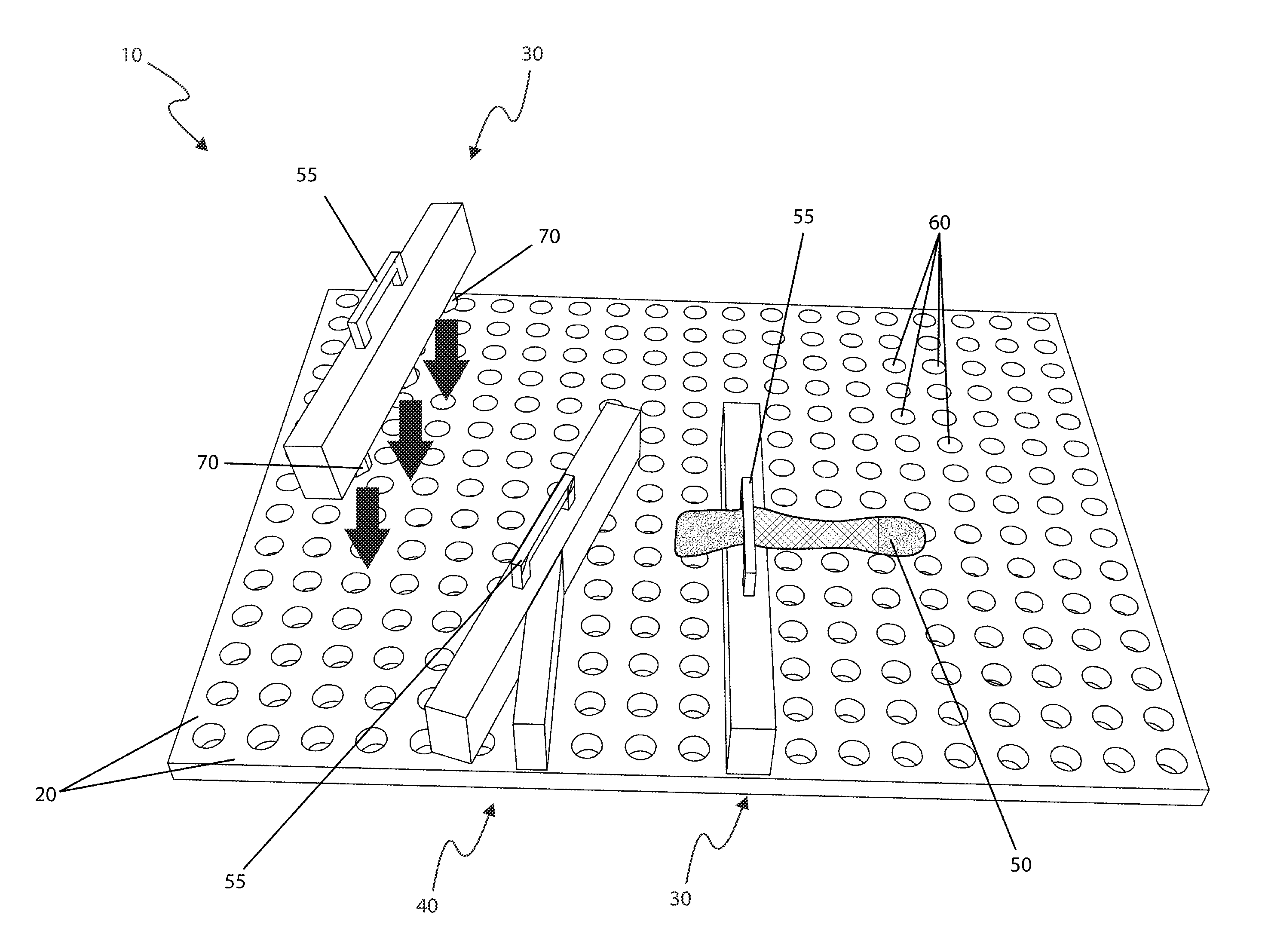
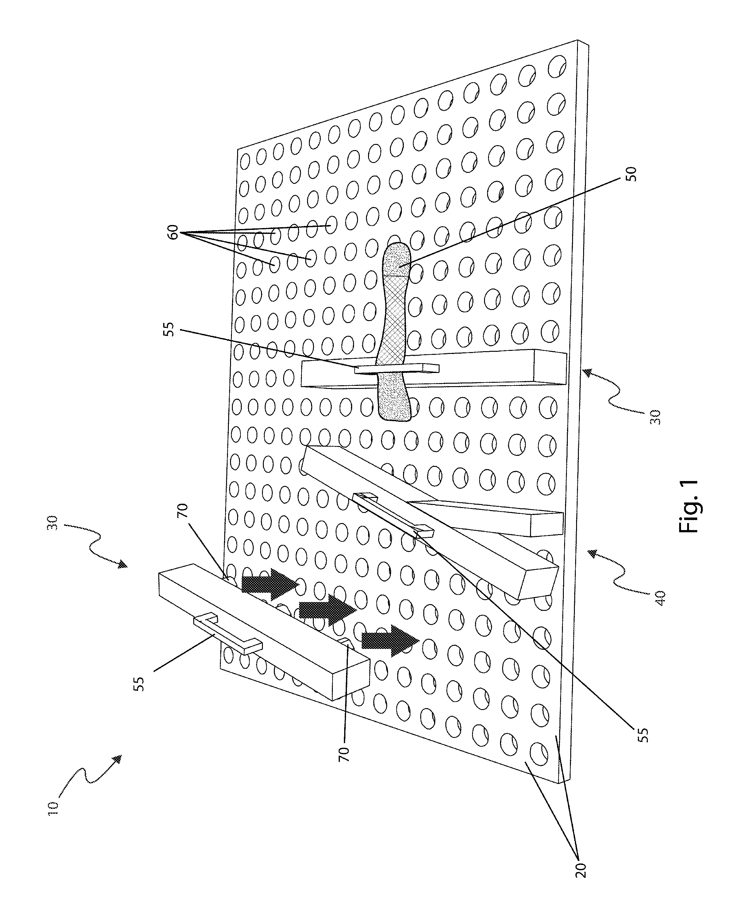
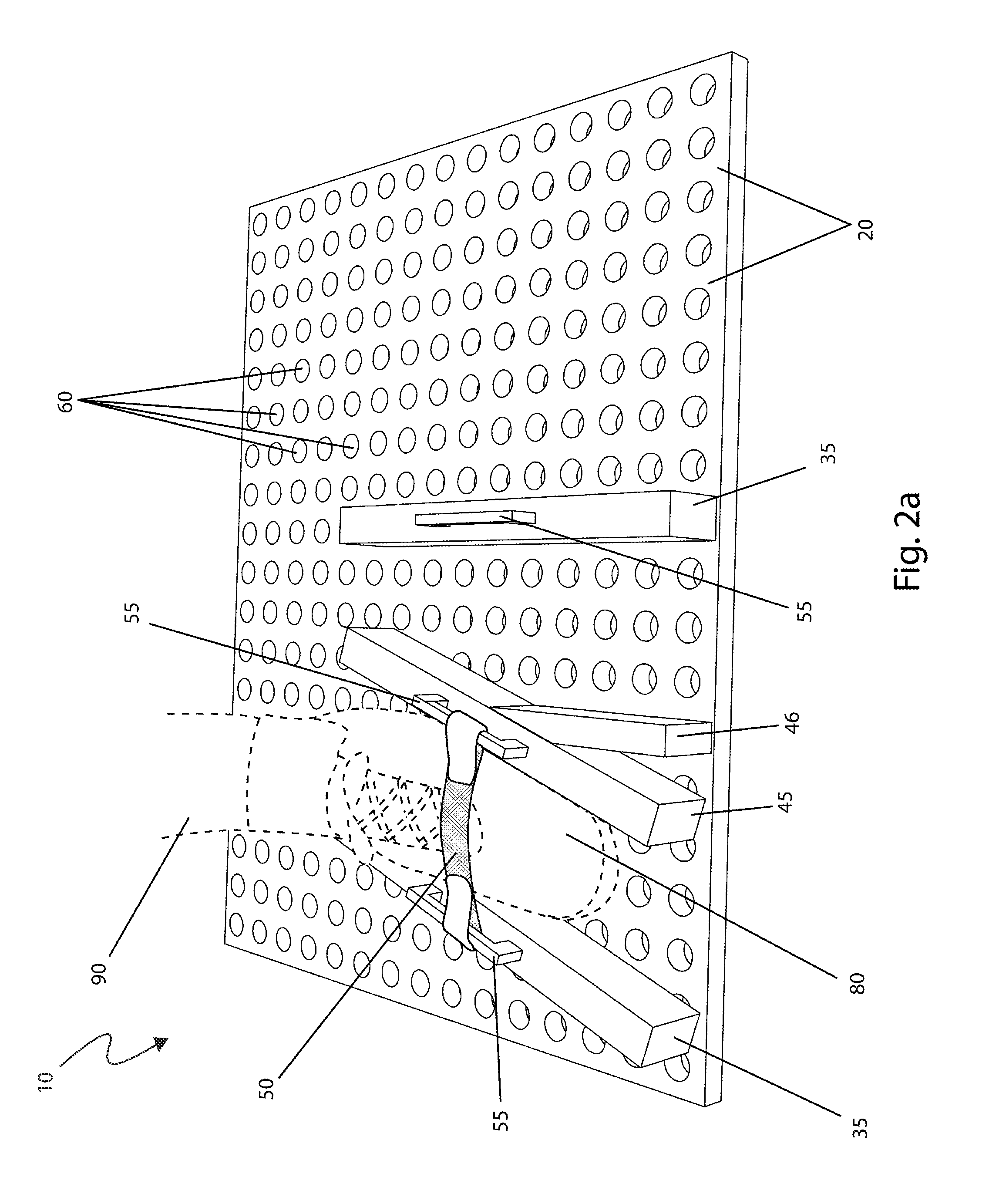
[0009]Another object of the present invention is to provide a plurality of rails with integral anchors which are removably attached to the board. These rails also include a plurality of apertures intended for use in securing the rails to the board, in a manner which allows these rails to be selectively oriented at alternate positions along the board.
[0014]Yet still another object of the present invention is to provide a method of utilizing the device in a way which allows a user to quickly, easily, and adaptably employ the device for purposes of achieving a neutral position for both foot and lower leg when in a sitting position in a manner that aids and accelerates the post-surgical recovery process.

Problems solved by technology

Many of these procedures are rather serious, resulting in a temporary loss of function and mobility.
However, many such devices are known to cause problems such as pinching, binding, and other nuisances.
Such discomforts prompt the user to respond to unpleasant stimuli in a way that is detrimental to the recovery effort.
The Krivosha device encompasses the user's ankle area, thereby limiting the field of motion.
Many of these devices are prone to discomforts, such as shifting, pinching, or binding.
Also, many of these devices do not provide for a means to discourage unnecessary movement of the lower leg.
Furthermore, many of these devices function in a manner that encourages the user to avoid discomfort by moving in a way which is detrimental to the recovery process.

Method used


Image

  • Lower leg and foot stabilizer
  • Lower leg and foot stabilizer
  • Lower leg and foot stabilizer

Examples


Embodiment Construction

[0038]The best mode for carrying out the invention is presented in terms of its preferred embodiment, herein depicted within FIGS. 1 through 4b. However, the invention is not limited to the described embodiment and a person skilled in the art will appreciate that many other embodiments of the invention are possible without deviating from the basic concept of the invention, and that any such work around will also fall under scope of this invention. It is envisioned that other styles and configurations of the present invention can be easily incorporated into the teachings of the present invention, and only one particular configuration shall be shown and described for purposes of clarity and disclosure and not by way of limitation of scope.

[0039]The terms “a” and “an” herein do not denote a limitation of quantity, but rather denote the presence of at least one of the referenced items.

[0040]The present invention describes a device and method for a lower leg and foot stabilizer (herein d...


PUM


Abstract

A device to hold one's foot in a neutral position while sitting in order to aid in healing includes a large plastic panel with a set of parallel plastic strips extending upward. These strips are adjustable upon the surface of the board using a series of small holes and corresponding pins. The strips are thus aligned to match the width of one's foot being held in a shoe. When aligned upon the floor, the foot, in a normal shoe without the use of a brace, is held in a neutral position which helps prevent contracture of the leg and foot muscles thus promoting faster healing after surgery. Additionally, the current device does not provide for pinching or twisting as commonly occurs with conventional prosthetic braces.

Description

RELATED APPLICATIONS[0001]The present invention was first described in a notarized Official Record of Invention on Jun. 9, 2008, that is on file at the offices of Montgomery Patent and Design, LLC, the entire disclosures of which are incorporated herein by reference.FIELD OF THE INVENTION[0002]The present invention relates generally to post-surgical recovery practices, and in particular, to a device for aiding in the stabilization of the lower leg and foot to expedite the post-surgical healing process.BACKGROUND OF THE INVENTION[0003]Thousands of persons a year undergo surgery on their feet or legs. Many of these procedures are rather serious, resulting in a temporary loss of function and mobility. Many common devices, such as prosthetic leg braces, are used in an attempt to expedite the healing process. However, many such devices are known to cause problems such as pinching, binding, and other nuisances. Such discomforts prompt the user to respond to unpleasant stimuli in a way tha...

Claims


Application Information

Patent Timeline
Patent Type & Authority Patents(United States)
IPC IPC(8): A61F5/37
CPCA61F5/37A61F5/0116
Inventor WILLIAMS, MICHAEL A.
Owner WILLIAMS MICHAEL A
Why Eureka
Try Eureka