Air circulation ports in rotary rock bit journal bearing

a technology of air circulation and journal bearing, which is applied in the direction of shafts, bearings, cutting machines, etc., can solve the problems of limiting the life of the bearing system of the rock bit, the bit can only operate for so long, and the damage to the bit may be considered sufficient, so as to maximize the surface area, reduce the area of machined recesses, and optimize the efficiency of the journal bearing

Active Publication Date: 2012-12-25
SANDVIK INTELLECTUAL PROPERTY AB
View PDF10 Cites 2 Cited by
  • Summary
  • Abstract
  • Description
  • Claims
  • Application Information

AI Technical Summary

Benefits of technology

[0012]In other aspects, embodiments disclosed herein relate to a method of optimizing the efficiency of a journal bearing for a rock bit, the method including reducing the area of machined recesses at the first and second air circulation port locations in the secondary thrust bearing surface and maximizing a surface area of a primary bearing surface and a secondary bearing surface, locating the air circulation ports in the primary and secondary bearing surfaces away from a highest loaded region of the surfaces, and locating a first air circulation port in an upper half of the secondary thrust bearing surface and locating a second air circulation port in a lower half of the secondary thrust bearing surface.

Problems solved by technology

However, the rock bit can only operate for so long before the wear and load on the bearing due to the applied forces causes sufficient damage to the bit to necessitate changing to a new bit.
Therefore, the bearing system may be considered the life-limiting component of the rock bit.
In hard rock formations, the thrust bearing surfaces are subjected to severe impact loads and frictional wear.
In some applications, the wear and damage of the thrust bearing surfaces causes failure of the bit even if the cutting elements are still intact.
Therefore, failure of the bearing system may be considered a premature failure of the bit.

Method used


Image

  • Air circulation ports in rotary rock bit journal bearing
  • Air circulation ports in rotary rock bit journal bearing
  • Air circulation ports in rotary rock bit journal bearing

Examples


Embodiment Construction

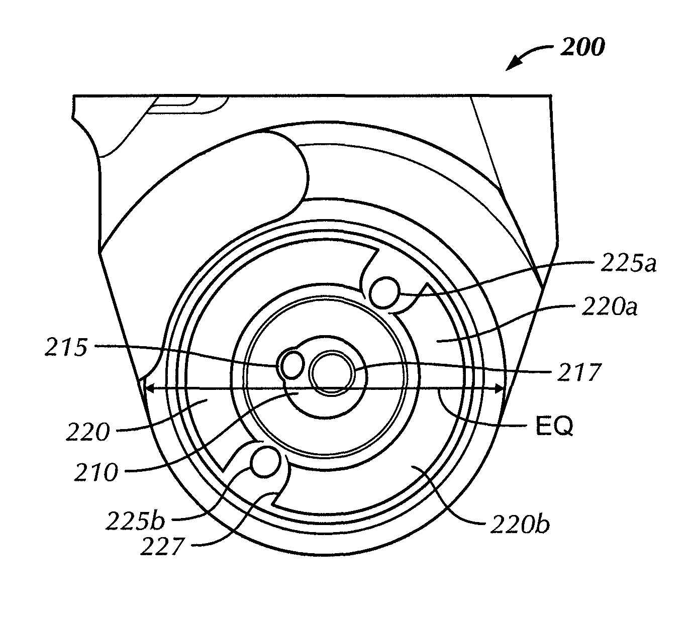
[0023]In one aspect, embodiments disclosed herein relate to improved thrust bearings and methods of providing improved thrust bearings in a roller rock bit. In particular, embodiments disclosed herein relate to optimizing locations of air circulation ports in roller rock bit journal bearings and maximizing bearing surface area to improve thrust bearing performance.

[0024]Embodiments of the present disclosure seek to improve the thrust bearing capacity by increasing the surface area available to sustain the thrust loads on the bearing surface in conjunction with optimizing locations of the air circulation ports in the thrust bearing surfaces. During the drilling operation, the thrust loading of the journal bearing is non-uniform, i.e., a portion of the thrust bearing is subjected to a higher load than the rest of the bearing surface. This is due the angle of contact between a roller cone attached to a leg of the rock bit and the formation during drilling. Because of the weight on the ...


PUM


Abstract

A thrust bearing system for a roller cone rock bit includes at least one roller cone disposed on a leg having an air channel therethrough, the thrust bearing system including a primary thrust bearing surface on the leg configured to contact a corresponding primary bearing surface on the roller cone, wherein the primary thrust bearing surface on the leg includes at least one air circulation port in fluid communication with the air channel. The thrust bearing system further includes a secondary thrust bearing surface on the leg configured to contact a corresponding secondary bearing surface on the roller cone, wherein the secondary thrust bearing surface on the leg includes at least two air circulation ports located at specified locations in the secondary bearing surface and in communication with the air channel, and wherein a first circulation port is located in an upper half of the secondary thrust bearing surface and a second circulation port is located in a lower half of the secondary thrust bearing surface.

Description

BACKGROUND[0001]1. Field of the Disclosure[0002]Embodiments disclosed herein relate generally to rock drill bits. More particularly, embodiments disclosed herein relate to improved thrust bearings and methods of providing improved thrust bearings for rock drill bits.[0003]2. Background Art[0004]Drilling into rock formations to enable explosive charges to be placed for excavating ore in open-cut mining operations may be carried out by roller air blast drills. Air at high pressure (typically 40 psi) and volume (750 to 2000 cubic feet a minute (cfm)) may be delivered through a bore in the drill string to a rock drill bit. The air supplied to the rock drill bit, which may, for example, be a blade or roller type bit, exits from orifices or nozzles in the bit, cools the bearings of the bit and conveys the debris created by the drilling away from the drilling workface up the borehole. This debris may travel up the borehole at a typical (bailing) velocity of 5,000 to 7,000 feet per minute d...

Claims


Application Information

Patent Timeline
Patent Type & Authority Patents(United States)
IPC IPC(8): F16C33/00F16C31/00E21B10/00
CPCE21B10/22E21B21/16E21B10/23
Inventor NAGARAJ, MAHAVIRMARCUS, JEREMYSHOTTON, VINCENT WAYNEBHOITE, SAMEER
Owner SANDVIK INTELLECTUAL PROPERTY AB
Why Eureka
Try Eureka