V-shaped filter tank with produced water tanks arranged below filter tanks and working method thereof

A filter and pool technology, applied in the direction of separation methods, chemical instruments and methods, fixed filter elements, etc., can solve the problems of V-shaped filter with large floor area, large floor area, complex pool structure, etc. Achieve the effect of reducing the amount of excavated earthwork and foundation treatment area, reducing the occupied area, and reducing project investment

Pending Publication Date: 2020-03-06
鞍钢集团工程技术有限公司
View PDF9 Cites 2 Cited by
  • Summary
  • Abstract
  • Description
  • Claims
  • Application Information

AI Technical Summary

Problems solved by technology

After the investigation of the actual operation on the site, the above layout method has the following disadvantages: 1) The single pool area of ​​the V-shaped filter is larger than that of the ordinary filter, and because the drainage groove in the middle occupies a part of the area, the space cannot be obtained. Fully utilized, under the same filtration capacity, the V-shaped filter occupies a larger area; 2) Compared with other filters, the V-shaped filter has a much more complicated pool structure, and the construction is difficult. Large amount of excavated earthwork and large foundation treatment area, resulting in high project investment

Method used


Image

  • V-shaped filter tank with produced water tanks arranged below filter tanks and working method thereof
  • V-shaped filter tank with produced water tanks arranged below filter tanks and working method thereof
  • V-shaped filter tank with produced water tanks arranged below filter tanks and working method thereof

Examples


Embodiment Construction

[0027] The specific embodiment of the present invention will be further described below in conjunction with accompanying drawing:

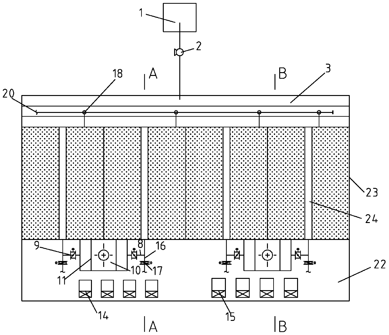
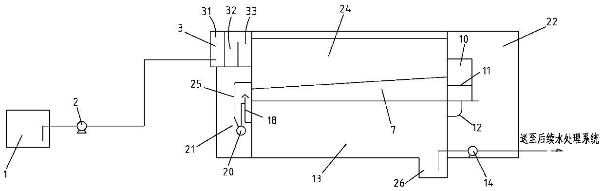
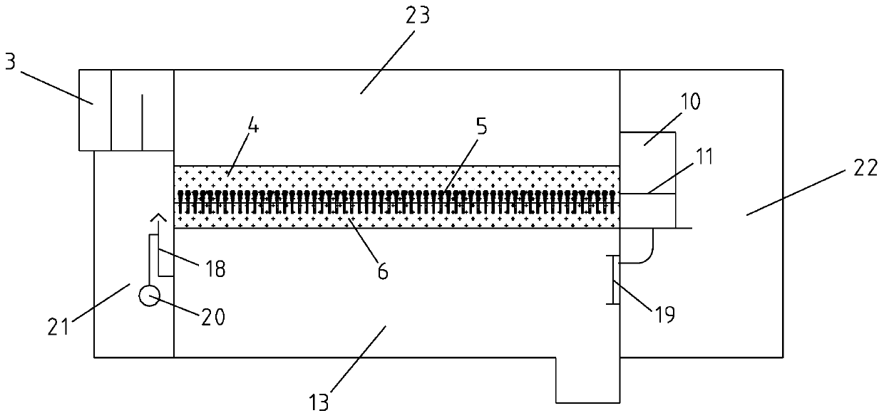
[0028] Such as Figure 1-Figure 3 As shown, a kind of water production pond of the present invention is located at the V-shaped filter pond below the filter pond, comprises the V-shaped filter pond that is made up of filter pond 23 and water production pond 13; The two ends of described filter pond 23 along the longitudinal direction are respectively The water inlet end and the water outlet end are respectively provided with a filter body on both sides of the center along the transverse direction, a water storage chamber 6 is arranged at the bottom of the filter body, and a filter head 5 is arranged on a filter plate between the water storage chamber 6 and the filter material 4; A drainage tank 24 is arranged between the pool body, and an air-water chamber 7 is arranged at the bottom of the drainage groove 24; the water storage chamber 6 and the a...


PUM


Abstract

The invention relates to a V-shaped filter tank with produced water tanks arranged below filter tanks and a working method thereof. A water storage chamber is arranged at the bottom of each filter tank body, and filter heads are arranged on a filter plate between the water storage chamber and a filter material; drainage grooves are arranged between the filter tank bodies, and gas-water chambers are arranged at the bottoms of the drainage grooves; the water storage chambers are communicated with the gas-water chambers through a plurality of holes on the side wall; produced water tanks are arranged below the filter tanks; water outlet wells and water supply pumps are arranged outside the filter tanks at the water outlet ends; the gas-water chambers are communicated with the produced water chambers through the water outlet wells, and the produced water tanks are connected to a subsequent water treatment system through a water outlet pipeline. According to the invention, the produced watertanks of the V-shaped filter tank are arranged below the filter tanks, the overall floor space is reduced, and the investment is low; through effluent weirs and corresponding communicating pipes, theeffluent water of the filter tanks can be conveyed into the produced water tanks below by means of gravity, and water supply pumps, backwashing water pumps and other equipment can be placed in a pumproom concentratedly, thus guaranteeing the function of the filter tanks, and not increasing the floor area.

Description

technical field [0001] The invention relates to the technical field of wastewater treatment and purification, in particular to a V-shaped filter tank with a water production tank arranged below the filter tank and a working method thereof. Background technique [0002] At present, the V-shaped filter commonly used in the wastewater treatment system of iron and steel enterprises is generally in the form of a side-by-side arrangement of the filter tank and the water production tank, that is, the water production tank is located on one side of the filter tank, and the filtered water enters the outlet tank through the filter head. Gravity flow into the production pond. After the investigation of the actual operation on the site, the above layout method has the following disadvantages: 1) The single pool area of ​​the V-shaped filter is larger than that of the ordinary filter, and because the drainage groove in the middle occupies a part of the area, the space cannot be obtained....

Claims


Application Information

Patent Timeline
Patent Type & Authority Applications(China)
IPC IPC(8): B01D29/03B01D29/68
CPCB01D29/031B01D29/68
Inventor 杨婷婷于丰浩冯占立杨冶张新宇乔世金梁英杰侯勇刘佳诚
Owner 鞍钢集团工程技术有限公司
Why Eureka
Try Eureka