Latch arrangement for cargo restraint

a technology of cargo restraints and latches, which is applied in the direction of load securing, transportation items, transportation and packaging, etc., can solve the problems of rattling noise in the transportation vehicle, the difficulty of mounting or connecting the restraint devices to the track, and the failure of flexible straps to achieve the effect of reducing the rattl

Active Publication Date: 2012-12-25
ANCRA INTERNATIONAL CORPORATON
View PDF78 Cites 7 Cited by
  • Summary
  • Abstract
  • Description
  • Claims
  • Application Information

AI Technical Summary

Benefits of technology

[0009]It is another object of the present invention to provide such a cargo restraint that is easily installed in the track and removable from the tracks and movable along the tracks to a desired location for restating the cargo.
[0010]It is another object of the present invention to provide such a restraint that may be securely held in the tracks when not restraining cargo so that there is no relative movement between the restraint and the tracks and / or the surface of the vehicle thereby eliminating rattle and undue wear or damage to the restraint and / or the vehicle.
[0015]The restraint according to the principals of the present invention has three basic positions when mounted on the track of a transportation vehicle. These three positions are the locked position, wherein the restraint and the bracket to which it is coupled is prevented from movement along the track, an engaged position wherein the restraint and the bracket are moveable along the track but the restraint is not fixed into a position on the track and a disengaged position wherein the restraint and the bracket to which it is attached may be readily removed from the track.
[0020]A tension stud is provided and the tension stud has a circular base portion configured to slidably move in the channel of the track along the connecting passageway thereof and a stem portion that is at least partially threaded extending from the base portion and the threaded portion may threadingly engage the threaded radially extending aperture in the body portion of the axle member and extend therethrough to regions external the axle member. A nut may be placed on the outer end of the threaded portion to aid in restraining the tension stud in the desired position in the axle member. The base portion clampingly engages the inside surface of the top wall of the track for the restraint in the locked position thereof to prevent relative movement of the restraint and the bracket to which it is attached along the track. The base member is free of clamping engagement with the track so as to be able to move in the channel of the track as the tension stud moves along the connecting passageway for the restraint in the engaged position and the disengaged position. The base portion of the tension stud has a diameter dimension that is less than the diameter dimension of the apertures in the track so that the base portion may be placed into the track as well as removed from the track at any of the apertures thereof for the condition of the base portion aligned with one of the apertures in the track.
[0032]The control member is then moved into the locked position of the restraint. In the locked position of the restraint, the locking cam surface bears against the upper surface of the top washer and compresses the spring against the bracket thereby forcing the base portion of the tension stud into clamping engagement with the inner surface of the top wall of the track. The control pins move along the guide surface toward the second end of the lift member to cause the locking cam surface to move into bearing relationship with the top washer thereby compressing the spring and bringing the base portion of the tension stud into the clamping engagement with the track and preventing any further movement of the restraint with respect to the track which also eliminates the rattle often present in prior restraint arrangements.

Problems solved by technology

Such flexible straps have not always been successful in restraining variously configured cargos against all undesired movements.
In some prior restraint devices heretofore proposed for use with restraining cargo in vehicles equipped with known track configurations, the restraint devices were difficult to mount on or in connection with the track as well as remove from the track.
Further, in such devices when the device was idle in the track and not in use for restraining the cargo, the devices would have some relative movement with respect to the track and / or the surface supporting the track.
Such relative movement often created rattling type noises in the transportation vehicle as well as possible undue wear or breakage of the device or damage to the vehicle structure or track.

Method used


Image

  • Latch arrangement for cargo restraint
  • Latch arrangement for cargo restraint
  • Latch arrangement for cargo restraint

Examples


Embodiment Construction

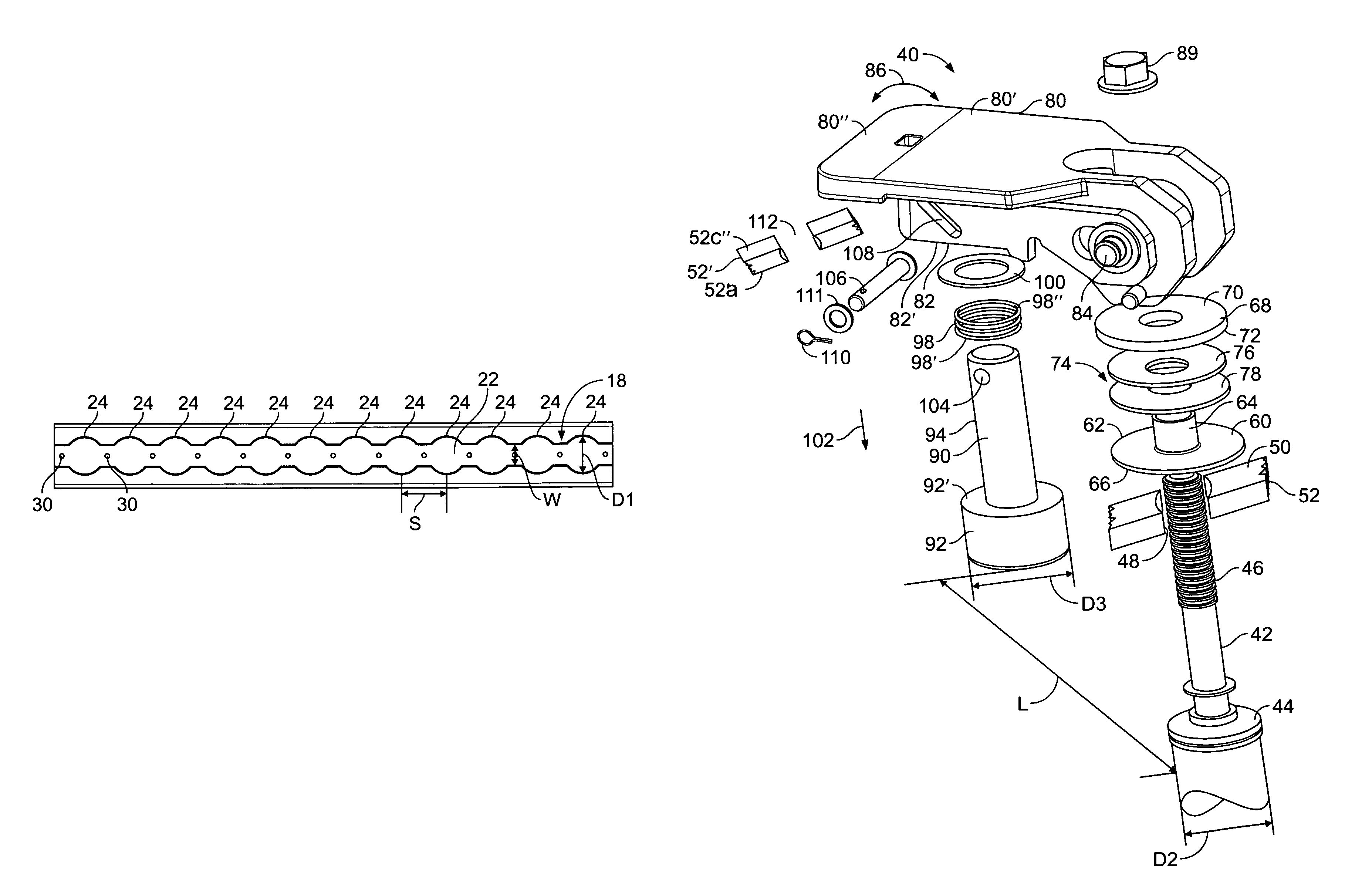
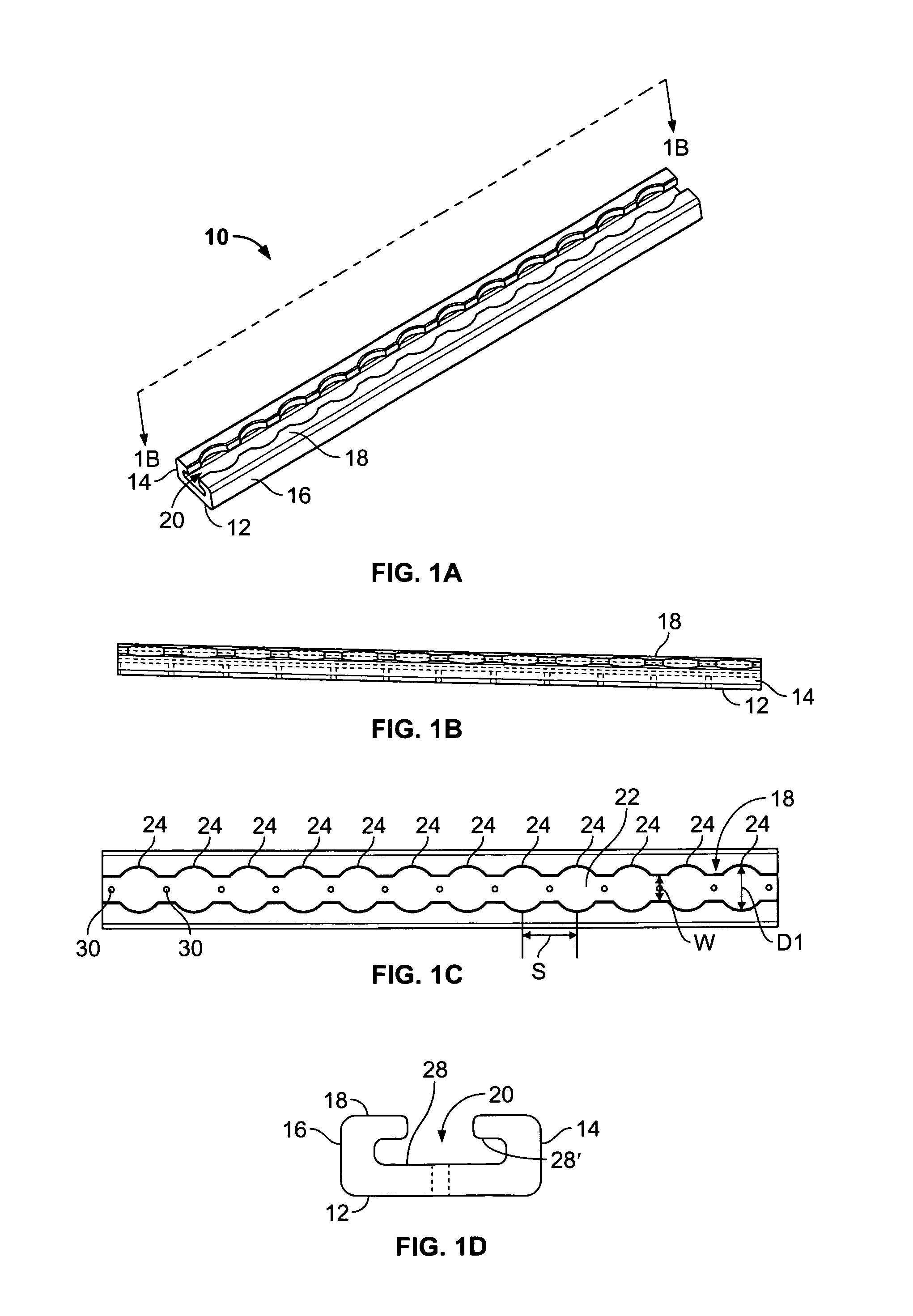
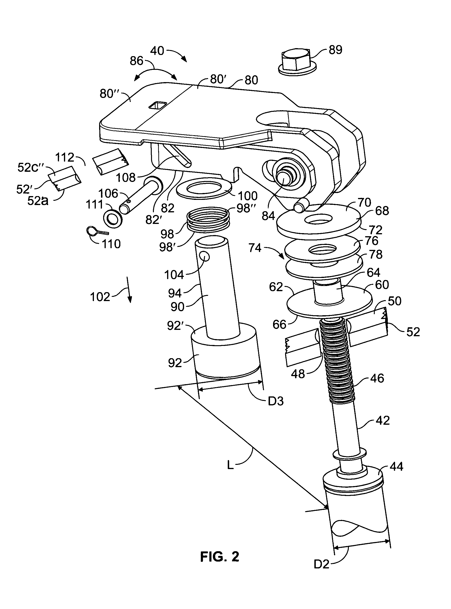
[0043]Referring now to the drawing, there is shown thereon a preferred embodiment of the present invention. As noted above, even though the track upon which the restraint of the present invention interacts is not part of the present invention but defines the environment in which the restraint operates to provide the desired objects of the present invention, the configuration of the track is described herein. FIGS. 1A, 1B, 1C and 1D illustrate a generally rectangular tubular track on which the restraint of the present invention may be mounted along with the bracket to which the restraint is coupled. The track, generally designated 10, has a modified, rectangular, tubular box shaped channel configuration.

[0044]The box channel track 10 has a bottom wall 12, a pair of opposed side walls 14 and 16 and a top wall 18 defining an interior open channel 20 therebetween. The top wall 18 of the track has a centrally located connecting passageway 22 of a first transverse width W extending along ...


PUM


Abstract

An improved cargo restraint for installation on a preselected track mounted in or on the surface of a vehicle carrying the cargo and the restraint is mounted on a bracket which abuts the cargo to restrain the movement of the cargo and the restraint is slidingly movable on the track and has a locking position on the track wherein the bracket restrains the cargo and the restraint has no relative movement with respect to the track or the bracket or the vehicle so that there is no rattling of the restraint when in the locked position.

Description

BACKGROUND OF THE INVENTION[0001]1. Field of the Invention[0002]This invention relates to the cargo restraint art and more particularly to a latch arrangement for restraining the horizontal and vertical movement of cargo in vehicles such as aircraft, trucks, railroad freight cars and the like.[0003]2. Description of the Prior Art[0004]In the above mentioned transportation of cargo by various vehicles such as cargo aircraft, vehicular trucks, railroad freight cars and the like it is often necessary to restrain the cargo from undesired movement during the transportation. In many applications, flexible cargo straps secured to the structure of the vehicle and wrapped around the cargo with the ends of the straps secured together have heretofore been utilized. Such flexible straps have not always been successful in restraining variously configured cargos against all undesired movements.[0005]In other applications, mechanical devices have been utilized for cargo restraint in vehicles, such...

Claims


Application Information

Patent Timeline
Patent Type & Authority Patents(United States)
IPC IPC(8): B60P7/08
CPCB60P7/0815B60P7/06B64D9/00
Inventor MORADIANS, EDWARDSHIM, KON
Owner ANCRA INTERNATIONAL CORPORATON
Why Eureka
Try Eureka