
Electrostatic particle charger, electrostatic separation system, and related methods

a technology of electrostatic separation and charger, which is applied in the field of material separation art, can solve the problems of concomitantly reducing the separation efficiency per, and achieve the effect of enhancing the charge on the particles

Inactive Publication Date: 2012-12-25
TAO DONGPING +1
View PDF48 Cites 6 Cited by
  • Summary
  • Abstract
  • Description
  • Claims
  • Application Information

AI Technical Summary

Benefits of technology

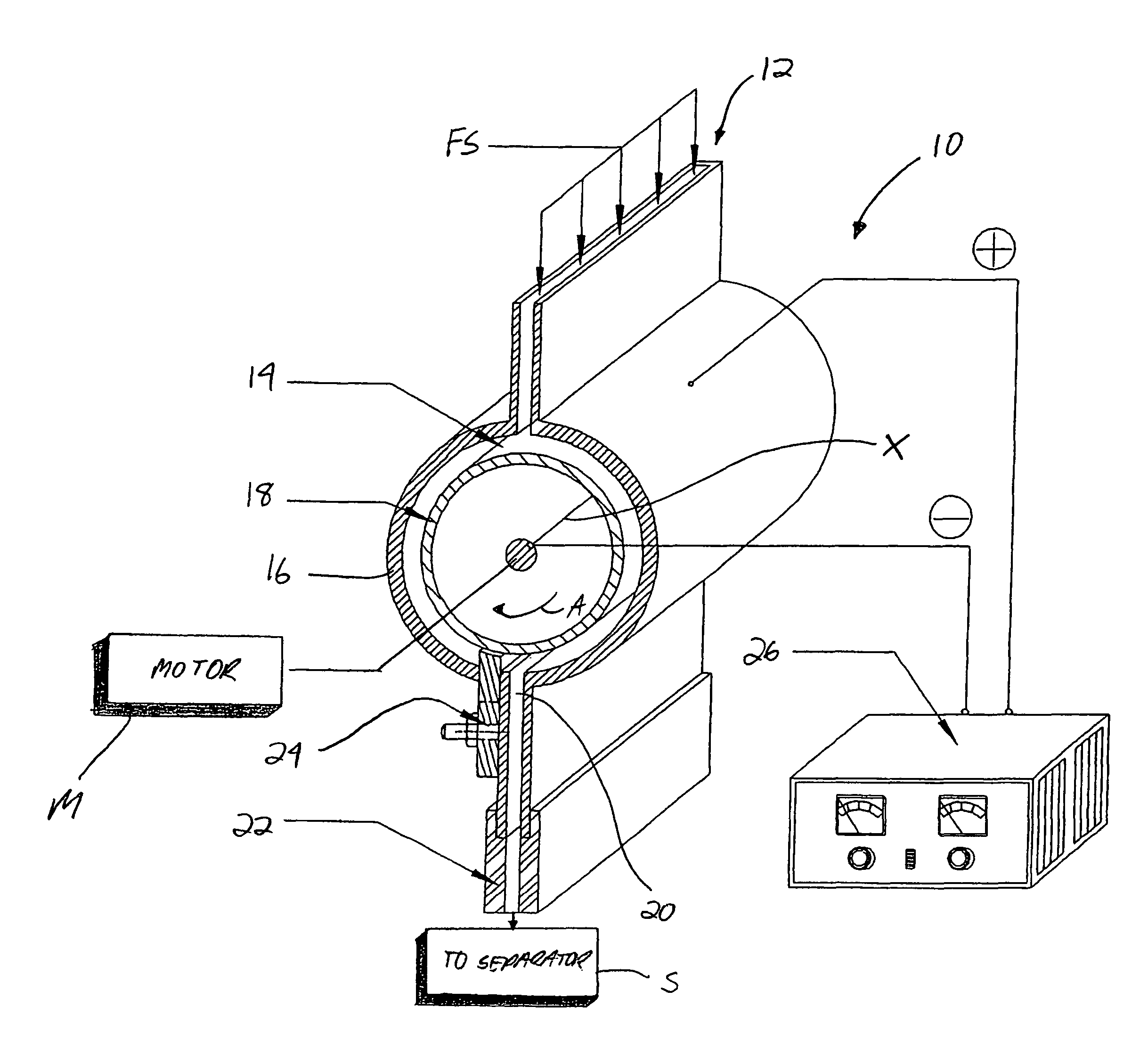
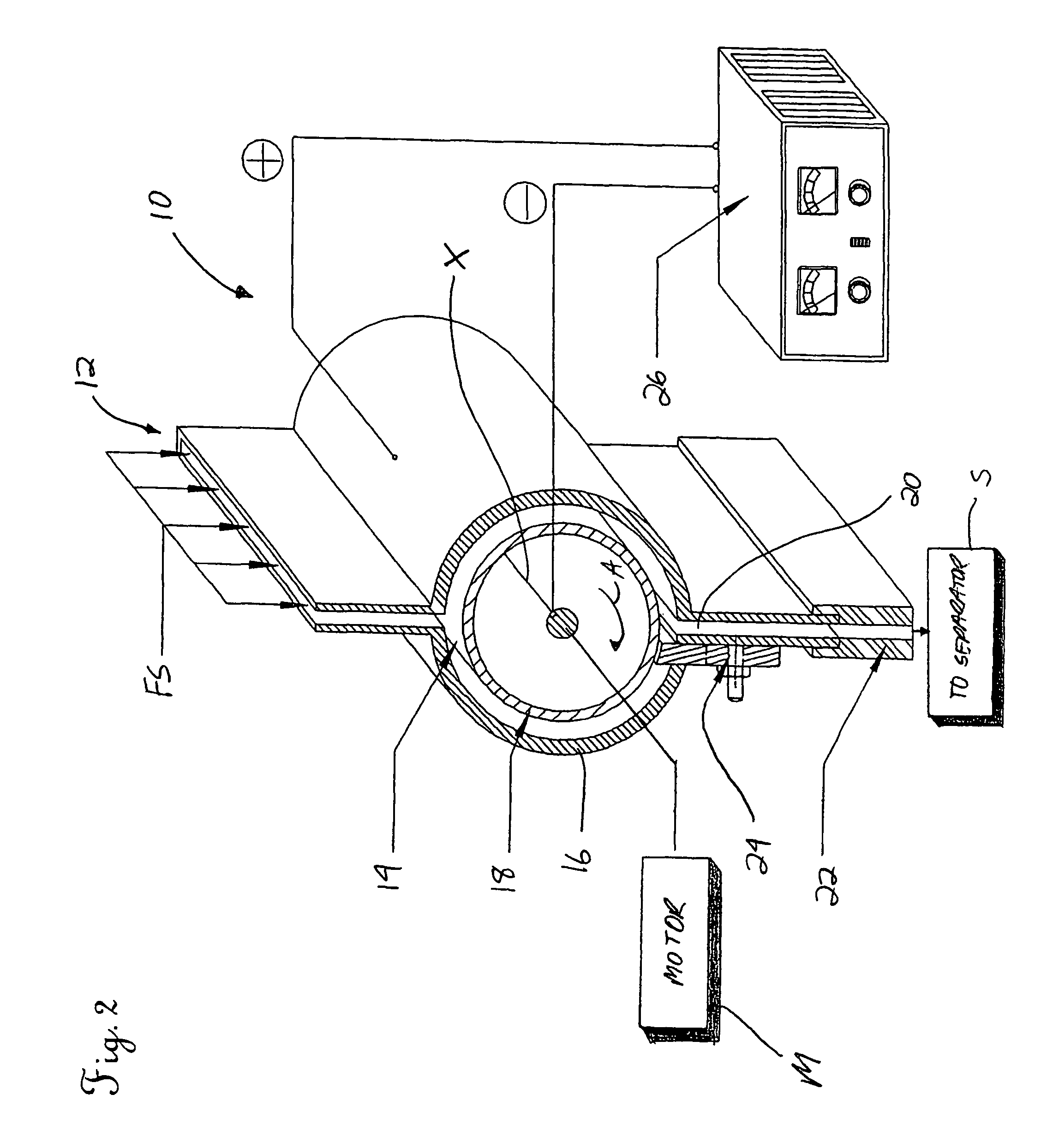
[0009]In the same or another embodiment, an electric field is provided in the chamber. Preferably, the electric field is created by a variable voltage source having a first lead connected to the rotor and a second lead connected to a wall of the chamber. The electric field helps to enhance the charging of certain types of particles.
[0013]In accordance with a fourth aspect of the invention, a method for separating electrostatically charged particles from a mixture is disclosed. The method comprises introducing the charged particles to a separation chamber including a positive grid electrode for attracting negatively charged particles and a negative grid electrode for attracting positively charged particles; and sweeping away corresponding particles from the grid electrodes using a straightened co-flow of a fluid, such as a gas. The step of actuating a rotor in a mixing chamber upstream of the separation chamber to enhance the charge on the particles in the mixture may also be performed.

Problems solved by technology

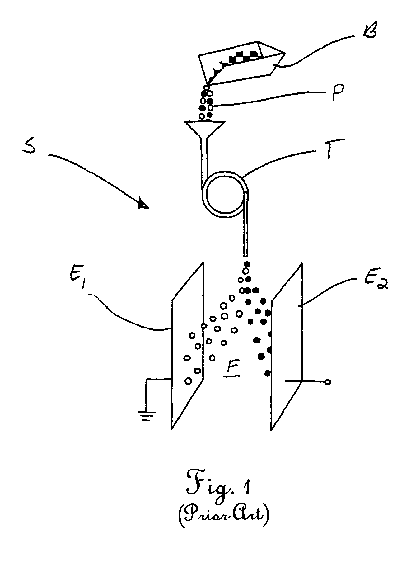
However, as a result of the inefficient charging resulting from the fact that not all particles make contact with the sidewalls of the tube T, weakly charged or charge-neutral particles may not be attracted and consequently simply pass through the separator S unaffected by the electric field F. While these “middling” particles (not shown in FIG. 1) may be separated during a second pass, this obviously decreases the efficiency of the separation operation.
Increasing the feed rate of the particles P may allow for more passes in a shorter period, but a concomitant decrease in the separation efficiency per pass results because of the shorter residence time of the particles in the electric field F.

Method used


Image

  • Electrostatic particle charger, electrostatic separation system, and related methods
  • Electrostatic particle charger, electrostatic separation system, and related methods
  • Electrostatic particle charger, electrostatic separation system, and related methods

Examples


example 1

Fly Ash Separation Result

[0037]

TABLE 1One-stage fly ash separationAshMiddlingTailing#LOI, %YieldLOI, %YieldLOI, %Yield#10.7544.571.9243.304.3112.13#20.9459.927.4925.6239.1914.46#31.1933.872.8238.0915.9828.04#41.2142.085.3745.8228.4712.10#53.6443.4114.9339.2241.4417.37

example 2

Fly Ash Separation Result

[0038]

TABLE 2Two-stage fly ash separationProductΣProductProductΣProductΣAshAsh, %Ash, %Yield, %Yield, %Recovery, %0.230.2336.0136.0138.851.040.4815.5851.5955.523.580.724.4856.0660.186.041.316.9062.9667.197.121.674.2067.1671.419.643.1114.8582.0185.9213.033.735.4587.4591.0427.134.502.9890.4393.3830.845.945.2495.6797.3042.387.524.34100.00100.00

example 3

Coal Cleaning Result

[0039]

TABLE 3Coal cleaningProductΣProductProductΣProductΣCombustibleΣAshAsh,Ash,Yield,Yield,Recovery,Rejection,%%%%%%3.443.4442.4042.4049.5691.617.824.8419.9462.3471.8182.6426.929.0714.7577.1084.8659.7837.8913.0212.2489.3494.0633.0953.9617.3810.66100.00100.000.00

[0040]Table 3 shows the results of coal cleaning obtained by a two-stage closed circuit test. The raw coal ash content is about 17%. For the product with 9.07% ash, an 84.86% of combustible recovery can be achieved with an ash rejection of 59.78%.


PUM


Abstract

In one aspect of the invention, a charger for use in a system for separating particles from a fluid flow is disclosed. In one embodiment, the charger comprises a body including an inlet for receiving the particles, a chamber in which the particles are received, and an outlet for discharging the particles. A rotor having a generally non-permeable surface is positioned in the chamber and rotated for contacting and charging the particles. In another aspect of the invention, grid electrodes with elongated fingers are proposed for use in a novel separation system. Related methods of charging and separating particles are also disclosed.

Description

[0001]This application claims the benefit of U.S. Provisional Patent Application Ser. No. 60 / 477,443 Jun. 10, 2003, the disclosure of which is incorporated herein by reference.TECHNICAL FIELD[0002]The present invention relates to the material separation art and, more particularly, to an improved particle charger or charging device, an improved separator, and related methods for electrostatically separating two species of particles from a particle mixture.BACKGROUND OF THE INVENTION[0003]“Dry” triboelectrostatic separation is widely used as an effective technique for separating different particulate solid components (“particles”) from a physical mixture entrained or carried in a driving fluid, such as air. Typical applications include the beneficiation of minerals, purification of foods, the recovery of valuable components from waste, and the sizing of particles in a particle mixture. This technology has gained widespread acceptance as providing a low cost, environmentally friendly t...

Claims


Application Information

Patent Timeline
Patent Type & Authority Patents(United States)
IPC IPC(8): B03C7/00B01DB01J19/08
CPCB03C3/08B03C3/10B03C3/15B03C3/49B03C7/006B03C7/06
Inventor TAO, DONGPINGJIANG, XINKAI
Owner TAO DONGPING
Learn More