Microwave oven with a regulation system using field sensors

a technology of field sensors and microwave ovens, applied in the direction of electric/magnetic/electromagnetic heating, dielectric heating, electrical apparatus, etc., can solve the problems of unsatisfactory heating uniformity, rotating or moving parts, unsatisfactory heating uniformity, etc., to improve the sensitivity of detecting mode distortion, the effect of improving energy efficiency

Active Publication Date: 2012-12-25
WHIRLPOOL CORP
View PDF8 Cites 29 Cited by
  • Summary
  • Abstract
  • Description
  • Claims
  • Application Information

AI Technical Summary

Benefits of technology

[0009]Generally, it is an object of the present invention to provide a microwave heating device improving heating uniformity.
[0022]According to an embodiment, the additional sensor is arranged at a location corresponding to a minimum (or comparatively low) field strength for the mode fed from the first or second feeding port, which is advantageous in that the sensitivity in detecting a mode distortion is optimized, or at least improved. For example, in an extreme case of mode distortion, the strengths measured by the first and the additional field sensors may be reversed, wherein the first field sensor measures a minimum field strength and the additional field sensor measures a maximum field strength.

Problems solved by technology

As known to a person skilled in the art, uneven heating when using microwave energy may be due to the presence of hot and cold spots in the mode field.
Drawbacks of such techniques are that they are not fully satisfying in terms of heating uniformity and that they involve rotating or moving parts.
However, a drawback is that such a microwave oven requires a rather advanced structure for feeding the microwaves into the cavity of the microwave oven and a non-standard design of the cavity.

Method used


Image

  • Microwave oven with a regulation system using field sensors
  • Microwave oven with a regulation system using field sensors
  • Microwave oven with a regulation system using field sensors

Examples


Embodiment Construction

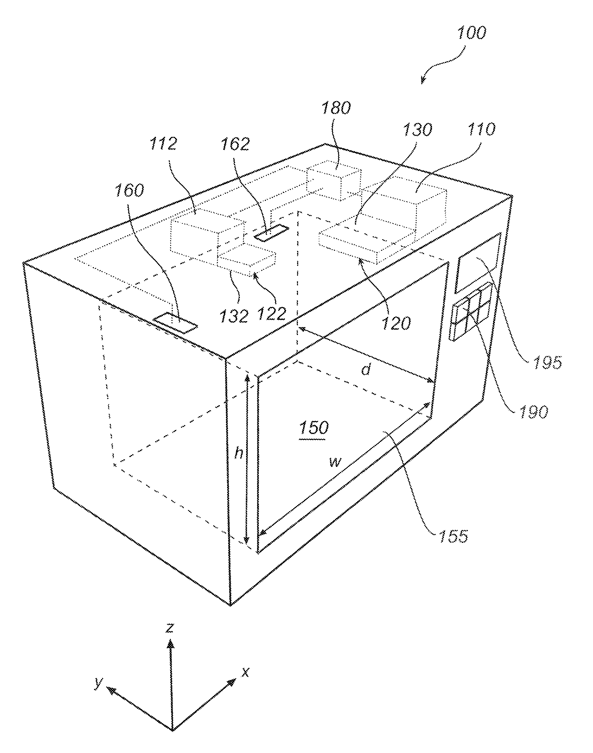
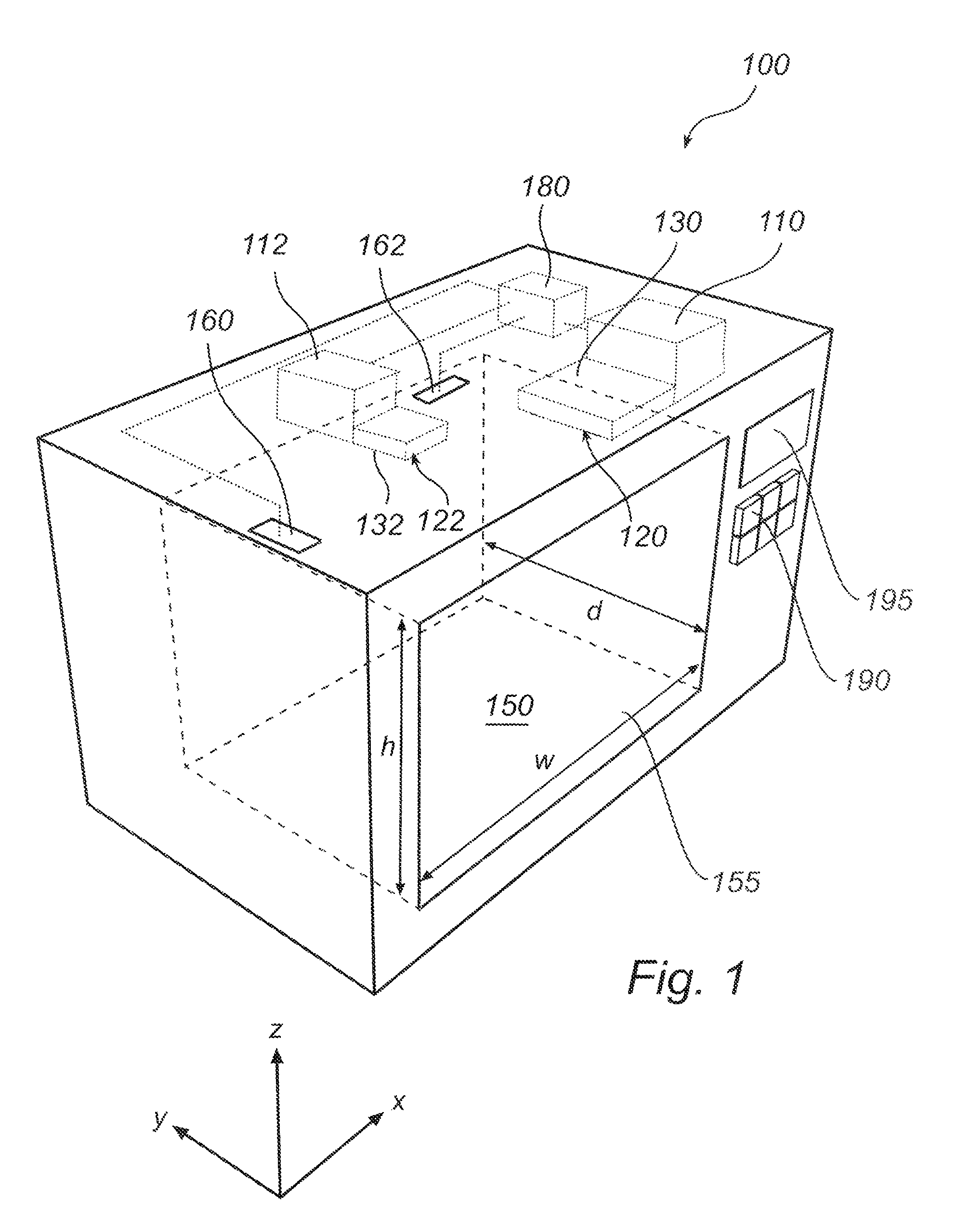
[0035]With reference to FIG. 1, there is shown a microwave heating device 100, e.g. a microwave oven, having features and functions according to an embodiment of the present invention.

[0036]The microwave oven 100 comprises a cavity 150 defined by an enclosing surface. One of the side walls of the cavity 150 may be equipped with a door 155 for enabling the introduction of a load, e.g. a food item, in the cavity 150. Further, the cavity 150 is provided with at least two feeding ports, a first feeding port 120 and a second feeding port 122, through which microwaves are fed into the cavity 150 of the microwave oven 100. The cavity 150 is generally made of metal.

[0037]Although the microwave oven 100 described with reference to FIG. 1 has a rectangular enclosing surface, it will be appreciated that the cavity of the microwave oven is not limited to such a shape and may, for instance, have a circular cross section, or other geometries describable in orthogonal curvilinear coordinates.

[0038...


PUM


Abstract

A microwave heating device and a method for heating a load using microwaves are provided. The microwave heating device comprises a cavity adapted to receive a load and at least two microwave sources for feeding microwave energy into the cavity through at least two feeding ports respectively. The microwave heating device further comprises at least two field sensors adapted to measure field strengths of the microwave energy in the cavity. A first field sensor is arranged at a first location for measuring the field strength representative of a mode fed from a first feeding port and a second field sensor is arranged at a second location for measuring the field strength representative of a mode fed from a second feeding port. The microwave heating device further comprises a control unit connected to the microwave sources and the field sensors for regulating the microwave sources based on the measured field strengths. The present invention is advantageous in that it enables uniform heating of the load in the cavity.

Description

BACKGROUND OF THE INVENTION[0001]1. Field of the Invention[0002]The present invention relates to the field of microwave heating and in particular to regulation of microwave heating devices.[0003]2. Description of the Related Art[0004]The art of microwave heating involves feeding of microwave energy into a cavity. When heating a load in the form of e.g. food by means of a microwave heating device, there are a number of aspects which have to be considered. Most of these aspects are well-known to those skilled in the art and include, for instance, the desire to obtain uniform heating of the food at the same time as a maximum amount of available microwave power is absorbed in the food to achieve a satisfactory degree of efficiency.[0005]As known to a person skilled in the art, uneven heating when using microwave energy may be due to the presence of hot and cold spots in the mode field. Traditional solutions to eliminate, or reduce, the effect of hot and cold spots are the use of a turnt...

Claims


Application Information

Patent Timeline
Patent Type & Authority Patents(United States)
IPC IPC(8): H05B6/68
CPCH05B6/74
Inventor NORDH, ULF ERIKNIKLASSON, OLLEHALLGREN, FREDRIKCARLSSON, HAKAN
Owner WHIRLPOOL CORP
Why Eureka
Try Eureka